
| Categories | Carrier HVAC Manuals |
|---|---|
| Document Type | Heating, Ventilating and Air Conditioning Manual Free Download. HAVC Operator's Instruction Manual. |
| Tags | Carrier 58D, Carrier 58S |
| Download File |
|
| Language | English |
| Product Brand | Carrier. Support Phone Number: In North America, please call 1-800-CARRIER for immediate customer assistance from 8:00a -5:00p (EST) weekdays , Heating, Ventilating and Air Conditioning - HVAC |
| Document File Type | |
| Publisher | corp.carrier.com |
| Wikipedia's Page | Carrier Corporation |
| Copyright | Attribution Non-commercial |
Pressure Switch Kit Cancels: 40395DP11-A IIK 375A-40-3 8-15-93 Installation Instructions Part No. 306621-752 NOTE: Read the entire instruction manual before starting the installation. INTRODUCTION This instruction covers the installation of pressure switch kit Part No. 306621-752 in induced-combustion furnaces models 375A, 376A, 376B, 395A, 395B, 397H, 58DH, 58DHB, 58SC, 58SS, and 58SSB. SAFETY CONSIDERATIONS Installing and servicing heating equipment can be hazardous due to gas and electrical components.
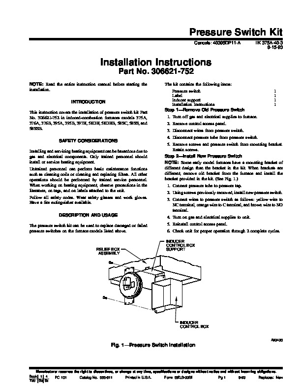
Only trained personnel should install or service heating equipment. Untrained personnel can perform basic maintenance functions such as cleaning coils or cleaning and replacing filters. All other operations should be performed by trained service personnel. When working on heating equipment, observe precautions in the literature, on tags, and on labels attached to the unit. Follow all safety codes. Wear safety glasses and work gloves. Have a fire extinguisher available. DESCRIPTION AND USAGE The pressure switch kit can be used to replace damaged or failed pressure switches on the furnace models listed above. The kit contains the following items: Pressure switch Label Inducer support Installation Instructions Step 1–Remove Old Pressure Switch 1. Turn off gas and electrical supplies to furnace. 2. Remove control access panel. 3. Disconnect wires from pressure switch. 4. Disconnect pressure tube from pressure switch. 5. Remove screws and pressure switch from mounting bracket. Retain screws. Step 2–Install New Pressure Switch NOTE: Some early model furnaces have a mounting bracket of different design than the bracket in the kit. When brackets are different, remove old bracket from the furnace and install the bracket provided in the kit. (See Fig. 1.) 1. Connect pressure tube to pressure tap. 2. Using screws previously removed, install new pressure switch. 3. Connect wires to pressure switch as follows: yellow wire to NC terminal, orange wire to C terminal, and brown wire to NO terminal. 4. Turn on gas and electrical supplies to unit. 5. Reinstall control access panel. 6. Check unit for proper operation through 2 complete cycles. INDUCER CONTROL BOX SUPPORT 1 RELIEF BOX ASSEMBLY INDUCER CONTROL BOX A93430 Fig. 1–Pressure Switch Installation Manufacturer reserves the right to discontinue, or change at any time, specifications or designs without notice and without incurring obligations. Book 1 4 PC 101 Catalog No. 565-811 Printed in U.S.A. Form 58D,S-33SI Pg 1 8-93 Replaces: New Tab 6a 8a 1993 Carrier Corporation 15095 Manufacturer reserves the right to discontinue, or change at any time, specifications or designs without notice and without incurring obligations. Book 1 4 PC 101 Catalog No. 565-811 Printed in U.S.A. Form 58D,S-33SI Pg 2 8-93 Replaces: New Tab 6a 8a