| Categories | Carrier HVAC Manuals |
|---|---|
| Document Type | Heating, Ventilating and Air Conditioning Manual Free Download. HAVC Operator's Instruction Manual. |
| Tags | Carrier 58CTS |
| Download File |
|
| Language | English |
| Product Brand | Carrier. Support Phone Number: In North America, please call 1-800-CARRIER for immediate customer assistance from 8:00a -5:00p (EST) weekdays , Heating, Ventilating and Air Conditioning - HVAC |
| Document File Type | |
| Publisher | corp.carrier.com |
| Wikipedia's Page | Carrier Corporation |
| Copyright | Attribution Non-commercial |
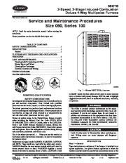
58CTS 2-Speed, 2-Stage Induced-Combustion Deluxe 4-Way Multipoise Furnace Visit www.carrier.com Service and Maintenance Procedures Size 090, Series 100 NOTE: Read the entire instruction manual before starting the installation. These procedures are for size 88,000 Btuh input unit. TABLE OF CONTENTS SAFETY CONSIDERATIONS .1 INTRODUCTION 1 General 1 ELECTROSTATIC DISCHARGE (ESD) PRECAUTIONS PROCEDURE 2 CARE AND MAINTENANCE .2 Cleaning And/Or Replacing Air Filter .2 Blower Motor and Wheel .3 Cleaning Heat Exchanger .4 Electrical Controls and Wiring .5 WIRING DIAGRAMS .7 TROUBLESHOOTING .7 CERTIFIED ® A00353 Fig.
1–Model 58CTS Multipoise REGISTERED QUALITY SYSTEM SAFETY CONSIDERATIONS Installing and servicing heating equipment can be hazardous due to gas and electrical components. Only trained and qualified personnel should install, repair, or service heating equipment. Untrained personnel can perform basic maintenance functions such as cleaning and replacing air filters. Observe precautions in the literature, on tags, and labels attached to or shipped with the unit and other safety precautions that may apply. Follow all safety codes. In the United States, follow all safety codes including the National Fuel Gas Code (NFGC) NFPA 54-1999/ANSI Z223.1-1999. In Canada, refer to the CAN/CGAB149.1- and .2-M95 National Standard of Canada, Natural Gas and Propane Installation Codes (NSCNGPIC). Wear safety glasses and work gloves. Have fire extinguisher available during start-up and adjustment procedures and service calls When you see this symbol on This is the safety-alert symbol the furnace and in instructions or manuals, be alert to the potential for personal injury. Understand the signal words DANGER, WARNING, CAUTION, and NOTE. These words are used with the safety-alert symbol. DANGER identifies the most serious hazards which will result in severe personal injury or death. WARNING signifies a hazard which could result in personal injury or death. CAUTION is used to identify unsafe practices which would result in minor personal injury or product and property damage. NOTE is used to highlight suggestions which will result in enhanced installation, reliability, or operation. The ability to properly perform maintenance on this equipment requires certain knowledge, mechanical skills, tools, and equipment. If you do not possess these, do not attempt to perform any maintenance on this equipment other than those procedures recommended in the User’s Manual. FAILURE TO FOLLOW THIS WARNING COULD RESULT IN POSSIBLE DAMAGE TO THIS EQUIPMENT, SERIOUS PERSONAL INJURY, OR DEATH. Label all wires prior to disconnection when servicing controls. Wiring errors can cause improper and dangerous operation. Step 1–General INTRODUCTION These instructions are written as if the furnace is installed in an upflow application. An upflow furnace application is where the blower is located below the combustion and controls section of the Manufacturer reserves the right to discontinue, or change at any time, specifications or designs without notice and without incurring obligations. Book 1 4 PC 101 Catalog No. 535-80008 Printed in U.S.A. Form 58CTS-1SM Pg 1 11-00 Replaces: New Tab 6a 8a furnace, and conditioned air is discharged upward. Since this furnace can be installed in any of the 4 positions shown in Fig. 2


