

| Categories | Carrier HVAC Manuals |
|---|---|
| Document Type | Heating, Ventilating and Air Conditioning Manual Free Download. HAVC Operator's Instruction Manual. |
| Tags | Carrier 24ABB |
| Download File |
|
| Language | English |
| Product Brand | Carrier. Support Phone Number: In North America, please call 1-800-CARRIER for immediate customer assistance from 8:00a -5:00p (EST) weekdays , Heating, Ventilating and Air Conditioning - HVAC |
| Document File Type | |
| Publisher | corp.carrier.com |
| Wikipedia's Page | Carrier Corporation |
| Copyright | Attribution Non-commercial |
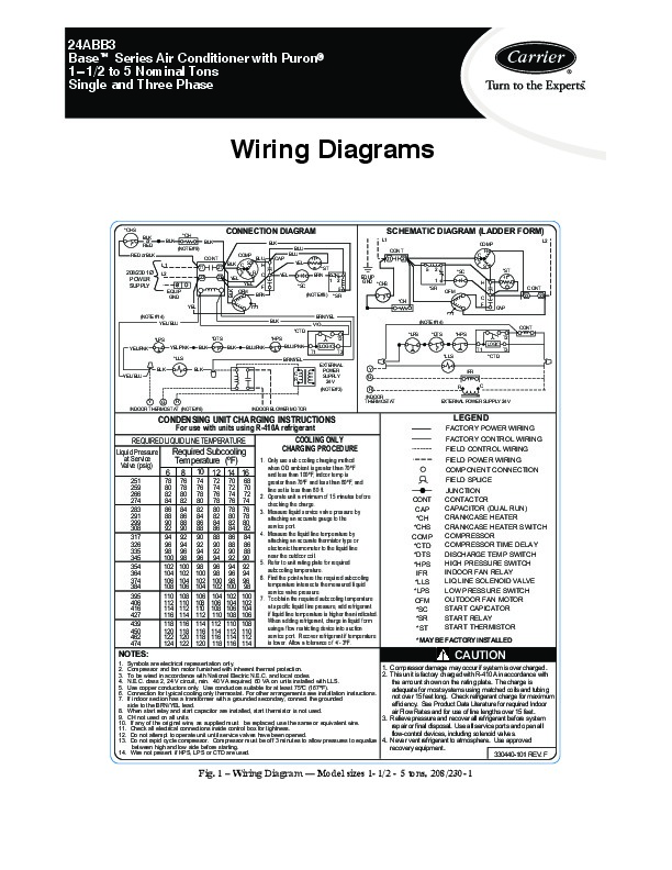
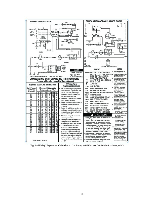
24ABB3 Baset Series Air Conditioner with Puronr 1 1/2 to 5 Nominal Tons Single and Three Phase Wiring Diagrams *CHS BLK or RED RED or BLK L1 *CH BLK (NOTE #9) COMP BLU CONT BLK C S H 21 11 R C 23 YEL 23 EQUIP GND YEL (NOTE #14) YEL/ BLU *LPS YEL/PNK YEL/PNK *LLS BLK YEL/ BLU BLK BLK *DTS BLK BLU/PNK BLK *CTD *HPS BLU/PNK T1 BRN/YEL C R EXTERNAL POWER SUPPLY 24 V (NOTE #3) Y G R INDOOR THERMOSTAT R C LOGIC T3 *LLS IFR T2 BRN/YEL VIO *LPS (NOTE #14) CONT *DTS *HPS LOGIC T1 * CTD T3 T2 BLK CONNECTION DIAGRAM BLK CAP YEL *SC (NOTE #8) BLU BLU YEL +t *ST BRN 1 2 5 *SR SCHEMATIC DIAGRAM (LADDER FORM) L1 CONT 11 21 5 EQUIP GND *CHS 2 1 *SR *CH OFM C F CAP *SC H CONT 23 23 C COMP R S L2 208/230 1Ø POWER SUPPLY L2 *ST +t BLK YEL OFM F BRN Y R G INDOOR THERMOSTAT (NOTE #6) EXTERNAL POWER SUPPLY 24 V INDOOR BLOWER MOTOR For use with units using R-410A refrigerant COOLING ONLY REQUIRED LIQUID LINE TEMPERATURE CHARGING PROCEDURE Liquid Pressure Required Subcooling at Service Valve (psig) 251 259 266 274 283 291 299 308 317 326 335 345 354 364 374 384 395 406 416 427 439 450 462 474 CONDENSING UNIT CHARGING INSTRUCTIONS LEGEND FACTORY POWER WIRING FACTORY CONTROL WIRING FIELD CONTROL WIRING FIELD POWER WIRING COMPONENT CONNECTION FIELD SPLICE JUNCTION CONTACTOR CAPACITOR (DUAL RUN) CRANKCASE HEATER CRANKCASE HEATER SWITCH COMPRESSOR COMPRESSOR TIME DELAY DISCHARGE TEMP SWITCH HIGH PRESSURE SWITCH INDOOR FAN RELAY LIQ LINE SOLENOID VALVE LOW PRESSURE SWITCH OUTDOOR FAN MOTOR STAR.
Heating, Ventilating and Air Conditioning User Manual Free Download. HAVC Operator’s Manual. Auto AC Free Instruction Manual Download PDF.
Only use sub cooling charging method when OD ambient is greater than 70ºF and less than 100ºF, indoor temp is greater than 70ºF and less than 80ºF, and line set is less than 80 ft. 2. Operate unit a minimum of 15 minutes before checking the charge. 3. Measure liquid service valve pressure by attaching an accurate gauge to the service port. 4. Measure the liquid line temperature by attaching an accurate thermistor type or electronic thermometer to the liquid line near the outdoor coil. 5. Refer to unit rating plate for required subcooling temperature. 6. Find the point where the required subcooling temperature intersects the measured liquid service valve pressure. 7. To obtain the required subcooling temperature at specific liquid line pressure, add refrigerant if liquid line temperature is higher than indicated. When adding refrigerant, charge in liquid form using a flow restricting device into suction service port. Recover refrigerant if temperature is lower. Allow a tolerance of +/- 3ºF. CONT CAP *CH *CHS COMP *CTD *DTS *HPS IFR *LLS *LPS OFM *SC *SR *ST * MAY BE FACTORY INSTALLED NOTES: Symbols are electrical representation only. Compressor and fan motor furnished with inherent thermal protection. To be wired in accordance with National Electric N.E.C. and local codes. N.E.C. class 2, 24 V circuit, min. 40 VA required, 60 VA on units installed with LLS. Use copper conductors only. Use conductors suitable for at least 75ºC (167ºF). Connection for typical cooling only thermostat. For other arrangements see installation instructions. If indoor section has a transformer with a grounded secondary, connect the grounded side to the BRN/YEL lead. 8. When start relay and start capacitor are installed, start thermistor is not used. 9. CH not used on all units. 10. If any of the original wire, as supplied must be replaced, use the same or equivalent wire. 11. Check all electrical connections i ….. …