
| Categories | Carrier HVAC Manuals |
|---|---|
| Document Type | Heating, Ventilating and Air Conditioning Manual Free Download. HAVC Operator's Instruction Manual. |
| Tags | Carrier 24ACB6 |
| Download File |
|
| Language | English |
| Product Brand | Carrier. Support Phone Number: In North America, please call 1-800-CARRIER for immediate customer assistance from 8:00a -5:00p (EST) weekdays , Heating, Ventilating and Air Conditioning - HVAC |
| Document File Type | |
| Publisher | corp.carrier.com |
| Wikipedia's Page | Carrier Corporation |
| Copyright | Attribution Non-commercial |
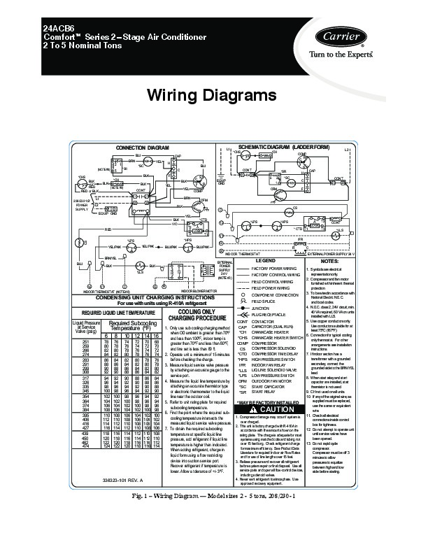
24ACB6 Comfortt Series 2 Stage Air Conditioner 2 To 5 Nominal Tons Wiring Diagrams CONNECTION DIAGRAM BLU BRN CAP YEL H C BLK *CH BLK (NOTE #9) 11 23 EQUIP GND YEL BLK VIO RED *LPS YEL/ PNK YEL/ PNK BLU/PNK *CTD Y2 T2 T3 CS *HPS BLU/PNK R BRN/YEL BLU BLK BLK C R EXTERNAL POWER SUPPLY 24 V (NOTE #3) INDOOR THERMOSTAT LOGIC T1 Y1 IFR G R C EXTERNAL POWER SUPPLY 24 V *LPS *HPS LOGIC * CTD T1 T3 *LLS T2 CONT BLK CONT 21 23 BLK YEL YEL BRN COMP OFM C CS F BLK C S R EQUIP GND BLU CONT 11 21 *SR 5 2 1 OFM *SC L1 SCHEMATIC DIAGRAM (LADDER FORM) *CHS *CH COMP R C S H C F CAP CONT 23 23 L2 2 1 (NOTE #8) *CHS BLK or RED RED or BLK 208/230 1Ø POWER SUPPLY L1 L2 5 *SR *SC LEGEND FACTORY POWER WIRING NOTES: 1.
Heating, Ventilating and Air Conditioning User Manual Free Download. HAVC Operator’s Manual. Auto AC Free Instruction Manual Download PDF.
Symbols are electrical *LLS representation only. FACTORY CONTROL WIRING 2. Compressor and fan motor FIELD CONTROL WIRING furnished with inherent thermal R Y2 Y1 C G protection. FIELD POWER WIRING INDOOR BLOWER MOTOR INDOOR THERMOSTAT (NOTE #6) 3. To be wired in accordance with COMPONENT CONNECTION National Electric N.E.C. CONDENSING UNIT CHARGING INSTRUCTIONS FIELD SPLICE and local codes. For use with units using R-410A refrigerant 4. N.E.C. class 2, 24V circuit, min. JUNCTION 40 VA required, 60 VA on units REQUIRED LIQUID LINE TEMPERATURE PLUG RECEPTACLE installed with LLS. 5. Use copper conductors only. CONT CONTACTOR Liquid Pressure Required Subcooling Use conductors suitable for at CAP CAPACITOR (DUAL RUN) at Service 1. Only use sub cooling charging method Temperature (ºF) least 75ºC (167ºF). Valve (psig) *CH CRANKCASE HEATER when OD ambient is greater than 70ºF 6. Connection for typical cooling *CHS CRANKCASE HEATER SWITCH and less than 100ºF, indoor temp is only thermostat. For other 251 78 76 74 72 70 68 COMP COMPRESSOR greater than 70ºF and less than 80ºF, arrangements see installation COMPRESSOR SOLENOID CS and line set is less than 80 ft. instructions. If indoor section has a *CTD COMPRESSOR TIME DELAY. Operate unit a minimum of 15 minutes transformer with a grounded HIGH PRESSURE SWITCH *HPS before checking the charge.