
| Categories | Carrier HVAC Manuals |
|---|---|
| Document Type | Heating, Ventilating and Air Conditioning Manual Free Download. HAVC Operator's Instruction Manual. |
| Tags | Carrier 24ANB1 |
| Download File |
|
| Language | English |
| Product Brand | Carrier. Support Phone Number: In North America, please call 1-800-CARRIER for immediate customer assistance from 8:00a -5:00p (EST) weekdays , Heating, Ventilating and Air Conditioning - HVAC |
| Document File Type | |
| Publisher | corp.carrier.com |
| Wikipedia's Page | Carrier Corporation |
| Copyright | Attribution Non-commercial |
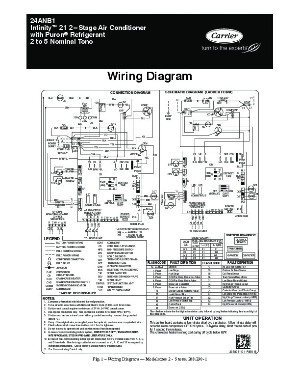
24ANB1 Infinityt 21 2 Stage Air Conditioner with Puronr Refrigerant 2 to 5 Nominal Tons Wiring Diagram CONNECTION DIAGRAM BLU CS BRN TRAN 24V RED RED *SR 2 1 5 COM 208V CCH BLK BLK BLK YEL BLK VIO L1 208/230 1Ø L2 POWER SUPPLY EQUIP GND RED/WHT BRN/YEL VS VR YEL/PNK YEL/PNK BLU/PNK BLU/PNK FAULT DEFINITION No 230v with Call to Run Outdoor Air Temp Sensor Coil Temp Sensor Temp Sensor Range Error Low Stage Thermal Cutout High Stage Thermal Cutout Contactor Shorted Contactor Open (No 230v to Comp) Low Stage Thermal Lockout (4 HRS) High Stage Thermal Lockout (4 HRS) Low Pressure Lockout (4 HRS) High Pressure Lockout (4 HRS) CAPACITOR CIRCUIT BOARD CRANKCASE HEATER CRANKCASE HEATER SWITCH SYSTEM COMMUNICATION COMPRESSOR * MAY BE FIELD INSTALLED NOTES: 1.
Compressor furnished with inherent thermal protection. To be wired in accordance with National Electric Code (N.E.C.) and local codes. Outdoor unit control requires a minimum of 27 VA, 24 VAC control power. Use copper conductors only. Use conductors suitable for at least 75ºC (167ºF). If indoor section has a transformer with a grounded secondary, connect the grounded side to “C “. 6. If any of the original wire, as supplied, must be replaced, use the same or equivalent wire. 7. Check all electrical connections inside control box for tightness. 8. Do not attempt to operate unit until service valves have been opened. 9. In case of a communicating indoor system, USE WITH INFINITY / EVOLUTION USER INTERFACE AS LISTED IN PRE-SALE LITERATURE ONLY. 10. In case of non-communicating indoor system disconnect factory provided