

| Categories | Carrier HVAC Manuals |
|---|---|
| Document Type | Heating, Ventilating and Air Conditioning Manual Free Download. HAVC Operator's Instruction Manual. |
| Download File |
|
| Language | English |
| Product Brand | Carrier. Support Phone Number: In North America, please call 1-800-CARRIER for immediate customer assistance from 8:00a -5:00p (EST) weekdays , Heating, Ventilating and Air Conditioning - HVAC |
| Document File Type | |
| Publisher | corp.carrier.com |
| Wikipedia's Page | Carrier Corporation |
| Copyright | Attribution Non-commercial |
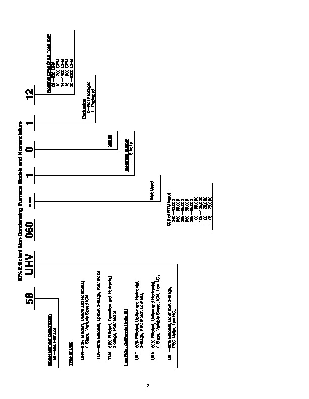
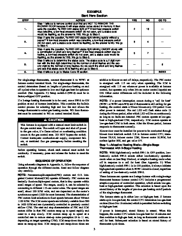
Deluxe 2-Stage Gas-Fired Induced-Combustion Furnaces With PSC or ICM Blower Motor Visit www.carrier.com Troubleshooting Guide NOTE: Read the entire instruction manual before starting the installation. SAFETY CONSIDERATIONS This symbol indicates a change since the last issue. INDEX PAGE Instructions .1 General 1-3 Furnace Model Nomenclature 2 Example 3 Sequence of Operation 3-6 Adaptive Heating Mode–Single-Stage Thermostat with 2-Stage Heating .3-4 Non-Adaptive Heating Mode–Two-Stage Thermostat with 2-Stage Heating .4 Cooling Mode 4-5 Continuous Blower Mode .5 Heat Pump Mode .5-6 Defrost .6 Component Test 6 Service Information Label .7 Start Here 8 Rapid Flashing LED 9 Improper Cooling Airflow 9-11 High-Heat Temperature Rise Too Low .12 Status Code 11–No Previous Code .12 Status Code 12–Blower On After Power Up 12-13 Status Code 13–Limit (LS) or Flame Rollout (FRS) Switch Lockout .13-15 Status Code 14–Ignition Lockout 15 Status Code 21–Gas Heating Lockout .15-16 Status Code 22–Abnormal Flame-Proving Signal 16 Status Code 23–Low-Heat Pressure Switch Did Not Open .16 Status Code 24–Secondary Voltage Fuse Is Open 17-19 Status Code 31–High-Heat Pressure Switch or Relay Did Not Close or Reopened .19-21 Status Code 32–Low-Heat Pressure, Draft Safeguard, or Auxiliary Limit (Downflow Only) Switch Did Not Close or Reopened .21-24 Status Code 33–Limit (LS) or Flame Rollout (FRS) Switch Is Open .24-26 Status Code 34–Ignition-Proving Fault 26-27 Status Code 43–Low-Heat Pressure, Draft Safeguard, or Auxiliary Limit Switch Open While High-Heat Pressure Switch Is Closed 27-29 Status Code 45–Replace Control .29 Cleanup and Start-Up Instructions 29 APPENDIX A–Board Layout and Wiring Schematics .30-32 APPENDIX B–ICM Blower Motor Description and Operation .33-37 APPENDIX C–Pressure Check Diagram .37-38 APPENDIX D–Quick Reference Troubleshooting Guide .38-39 APPENDIX E–Static Pressure Reading Location Diagrams .39-41 APPENDIX F–Thermostat Staging Algorithm 41-43 APPENDIX G–Quick Reference Information 43 APPENDIX H–Twinning .44-46 INSTRUCTIONS This guide uses your expertise and observations to lead you to the trouble spot as efficiently as possible.
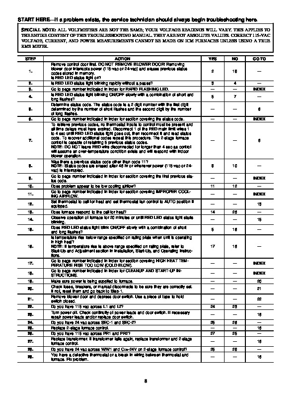
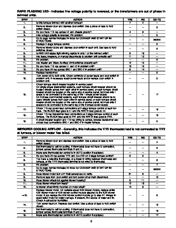
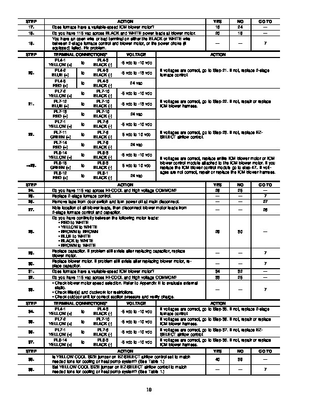
This is only intended as a guide and should not be used blindly. Your experience and expertise are of high value when troubleshooting this unit. Do not disregard all of your instincts. The 2-stage furnace control was designed with diagnostic capabilities built in. A RED LED is used to flash a status code which will lead you to 1 of the sections as listed in the Index. You should ALWAYS begin in the START HERE section (see Index for page number) which will guide you to the appropriate section where a minimal number of steps will be used to correct the problem. If you are very experienced at how this furnace operates, you can use the Quick Reference Troubleshooting Guide in Appendix D to isolate the problem. Once in a section, read the ACTION. An ACTION may have a number in the GO TO column. Do whatever the ACTION says, then proceed to the step indicated in the GO TO column. If the ACTION is a question (a question will have a number in the YES or NO column), answer it YES or NO. If the answer is YES, go to the step indicated in the YES column. If the answer is NO, go to the step indicated in the NO column. Let’s try our guide out using the EXAMPLE table on page 3, and see how it works. Suppose that the problem is a defective low-heat pressure switch (for example the contacts will not open). This is an internal problem and cannot simply be seen. We go to the START HERE section to Step 1. GENERAL The furnace must have a 115-vac power supply properly connected and grounded. Correct polarity must be maintained to enable gas heating operation. The gas service pressure must not exceed 0.5 psig (14-in.wc), and be no less than 0.16 psig (4.5-in.wc). Thermostat wire connections to furnace at R and W/W1 are the minimum required for gas heating operation. W2 must be connected for 2-stage heating thermostats. Y/Y2 and G are required to be connected to furnace for cooling and heat pumps. G is required for continuous fan. COM-24V is required for some clock thermostats. These connections must be made at 24-vac terminal block on furnace control. (See Appendix A.) O is required for heat pumps for ICM blower motors only.