
| Categories | Carrier HVAC Manuals |
|---|---|
| Document Type | Heating, Ventilating and Air Conditioning Manual Free Download. HAVC Operator's Instruction Manual. |
| Tags | Carrier 58DF |
| Download File |
|
| Language | English |
| Product Brand | Carrier. Support Phone Number: In North America, please call 1-800-CARRIER for immediate customer assistance from 8:00a -5:00p (EST) weekdays , Heating, Ventilating and Air Conditioning - HVAC |
| Document File Type | |
| Publisher | corp.carrier.com |
| Wikipedia's Page | Carrier Corporation |
| Copyright | Attribution Non-commercial |
Heat Exchanger Cell Replacement Kit Cancels: IIK 376C-40-14 IIK 373L-35-10 12-15-91 NOTE: Read the entire instruction before starting the installation. INTRODUCTION This instruction covers the installation of the heat exchanger cell kit Part No. in Models 373L, 376C, 383K, 394H, 395C, 396H, 58DFA, 58DHC, 58GFA, 58PAP, 58PAV, 58RAP, 58RAV, 58SSC, GA1A, and GA2A Gas Furnaces. SAFETY CONSIDERATIONS Installing and servicing of heating equipment can be hazardous due to gas and electrical components.
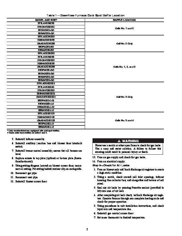
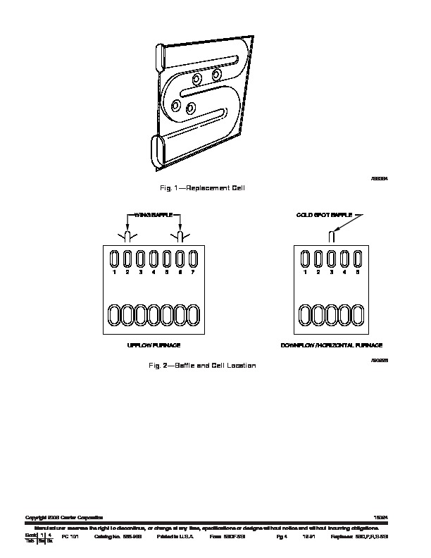
Only trained personnel should install or service heating equipment. Installation Instructions Part No. 310203-752 8. Remove auxiliary junction box and blower door interlock switch. 9. Remove screws securing cell panel to casing. 10. Upflow only–it may be necessary to remove two front screws of top plate. Downflow/horizontal only–remove two front screws of bottom plate. 11. Remove cell panel, with heat exchanger cells attached, through front of furnace. Step 2–Installation of Replacement Cell(s) 1. Determine which cell(s) need to be replaced. 2. Place heat exchanger on a flat surface with cell panel facing upward. 3. Remove screws from cell opening of cell(s) being replaced. Remove and replace one cell at a time. NOTE: The word “top” is stamped on cell inlet plates to aid in correct assembly. 4. Using care not to damage insulation around inlet and outlet openings, remove cell from cell panel. 5. Install new cell as follows: a. Center fiberglass insulation gasket over inlet and outlet openings of cell. b. Using short pieces of tape, tape each end of gasket to cell. c. Position cell under cell panel. d. Use an awl to align holes and start all eight screws. e. After all screws are started, check position of gaskets and cell inlet plates. When materials are properly aligned, tighten screws. 6. Cut away any insulation extending into cell openings. Do not drop pieces of insulation into cell. 7. Repeat Procedure 2, numbers 3 through 6, for additional cells being replaced. 8. Remove baffles from old cells (if applicable) and install on new cells. See Fig. 2, and Table 1 or 2 for baffle location. NOTE: Failure to install baffles in proper location may cause premature heat exchanger failure and/or main limit cycling. Step 3–Reinstall Heat Exchanger Assembly NOTE: Check the insulation around the top, bottom, and sides of the cell panel. The insulation must overlap enough to provide a good air seal when the assembly is installed. 1. Slide heat exchanger assembly into furnace, engaging cells into cell support. Avoid bending any internal casing baffles when assembling. 2. Using an awl, align holes and start screws. Ensure insulation stays in place, providing the necessary air seal. 3. Tighten screws into sides, top and bottom of cell panel. 4. If collector box sealant has been damaged, remove it and apply new sealant. Contact your distributor for proper sealant. Do not drop sealant into cell openings. Untrained personnel can perform basic maintenance functions such as cleaning coils, or cleaning and replacing filters. All other operations should be performed by trained service personnel. When working on heating equipment, observe precautions in the literature, and on tags and labels attached to the unit. Follow all safety codes. Wear safety glasses and work gloves. Have a fire extinguisher available. DESCRIPTION AND USAGE The heat exchanger cell replacement kit can be utilized to restore units having heat exchanger cells that require repair. Kit contains the following items: Heat exchanger cell Fiberglass gasket Presstite sealant Screw Installation Instruction INSTALLATION Step 1–Removal of Heat Exchanger Assembly 1. Turn off gas and electrical supplies to unit.