| Categories | Carrier HVAC Manuals |
|---|---|
| Document Type | Heating, Ventilating and Air Conditioning Manual Free Download. HAVC Operator's Instruction Manual. |
| Tags | Carrier 58DFA |
| Download File |
|
| Language | English |
| Product Brand | Carrier. Support Phone Number: In North America, please call 1-800-CARRIER for immediate customer assistance from 8:00a -5:00p (EST) weekdays , Heating, Ventilating and Air Conditioning - HVAC |
| Document File Type | |
| Publisher | corp.carrier.com |
| Wikipedia's Page | Carrier Corporation |
| Copyright | Attribution Non-commercial |
Inducer Motor Replacement Kit Cancels: IIK 373L-55-3 IIK 373L-55-4 3-97 Installation Instructions Part No. 318984-753 NOTE: Read the entire instruction manual before starting the installation. This symbol indicates a change since the last issue. SAFETY CONSIDERATIONS Installing and servicing heating equipment can be hazardous due to gas and electrical components. Only trained personnel should install or service heating equipment.
Heating, Ventilating and Air Conditioning User Manual Free Download. HAVC Operator’s Manual. Gas Furnace and AC Free Instruction Manual Download PDF.
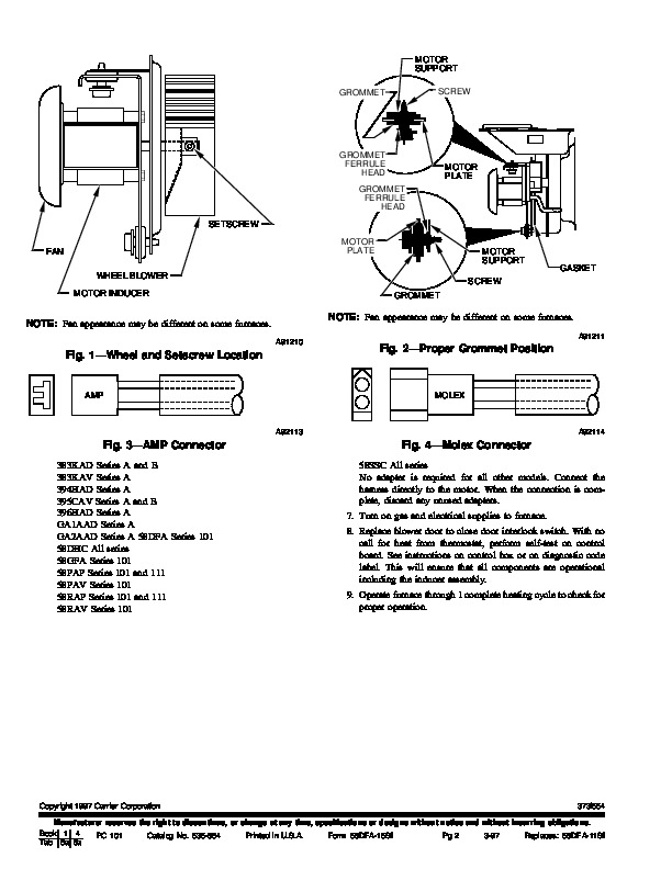
Untrained personnel can perform basic maintenance functions such as cleaning coils or cleaning and replacing filters. All other operations should be performed by trained service personnel. When working on heating equipment, observe precautions in the literature, on tags, and on labels attached to the unit. Understand the signal words DANGER, WARNING, and CAUTION. These words are used with the safety-alert symbol. DANGER identifies the most serious hazards which will result in severe personal injury or death. WARNING signifies a hazard which could result in personal injury or death. CAUTION is used to identify unsafe practices which would result in minor personal injury or product and property damage. NOTE is used to highlight suggestions which will result in enhanced installation, reliability, or operation. Follow all safety codes. Wear safety glasses and work gloves. Have a fire extinguisher available. 4. Unplug inducer motor. 5. Remove 3 assembly mounting screws and remove inducer motor assembly (motor, wheel, and mount) from inducer housing. Be careful not to damage inducer wheel during removal. 6. Measure location of wheel to motor support to use when reassembling. Using an allen wrench, loosen inducer wheel setscrew, and remove wheel from motor shaft. (See Fig. 1.) NOTE: If it is difficult to remove the wheel, lightly sand any scale or rust buildup from end of motor shaft. Apply a small amount of penetrating oil to shaft and hub. Tap lightly on hub only. Do not tap or pry on any other areas of wheel. If the wheel cannot be removed without damage, a replacement wheel is required. 7. Remove 3 motor grommet screws securing motor plate to motor support. 8. Remove 2 screws securing motor to motor plate. Step 2–Install New Inducer Motor Assembly 1. Attach new inducer motor assembly provided in kit to motor plate using original screws. 2. Attach motor support to motor plate through 3 grommets using 3 original screws. (See Fig. 2.) If there was a shaft seal between the plate and support, be certain it is moved to the new assembly. Tighten original screws firmly, but avoid stripping. 3. Reinstall inducer wheel. Wheel must be located as shown in Fig. 1. Align flat on shaft to line up with setscrew, then firmly tighten setscrew. 4. Install inducer motor assembly in inducer housing and fasten with 3 original mounting screws. Ensure that inducer motor ground wire is reinstalled under 1 of mounting screws.