| Categories | Carrier HVAC Manuals |
|---|---|
| Document Type | Heating, Ventilating and Air Conditioning Manual Free Download. HAVC Operator's Instruction Manual. |
| Tags | Carrier 58DH |
| Download File |
|
| Language | English |
| Product Brand | Carrier. Support Phone Number: In North America, please call 1-800-CARRIER for immediate customer assistance from 8:00a -5:00p (EST) weekdays , Heating, Ventilating and Air Conditioning - HVAC |
| Document File Type | |
| Publisher | corp.carrier.com |
| Wikipedia's Page | Carrier Corporation |
| Copyright | Attribution Non-commercial |
Heat Exchanger Cell Replacement Kit Cancels: 40397DP19-A IIK 375A-40-5 11-98 Installation Instructions Part No. 305078-751 NOTE: Read the entire instruction manual before starting the installation. This symbol indicates a change since the last issue. INTRODUCTION This instruction covers the installation of the heat exchanger cell kit Part No. 305078-751 in models 375A, 376A, 376B, 395A, 395B, 397H, 58DH, 58DHB, 58SC, 58SS, and 58SSB Gas Furnaces.
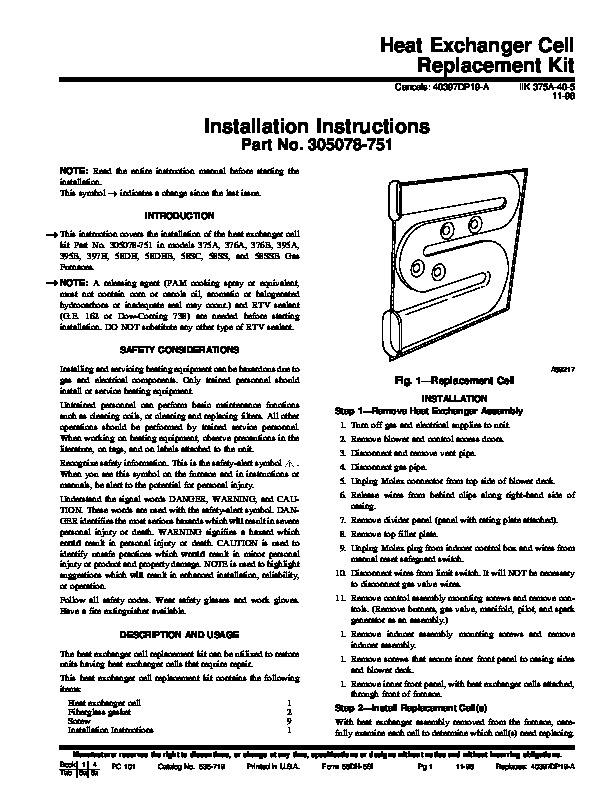
NOTE: A releasing agent (PAM cooking spray or equivalent, must not contain corn or canola oil, aromatic or halogenated hydrocarbons or inadequate seal may occur.) and RTV sealant (G.E. 162 or Dow-Corning 738) are needed before starting installation. DO NOT substitute any other type of RTV sealant. SAFETY CONSIDERATIONS Installing and servicing heating equipment can be hazardous due to gas and electrical components. Only trained personnel should install or service heating equipment. Untrained personnel can perform basic maintenance functions such as cleaning coils, or cleaning and replacing filters. All other operations should be performed by trained service personnel. When working on heating equipment, observe precautions in the literature, on tags, and on labels attached to the unit. Recognize safety information. This is the safety-alert symbol. When you see this symbol on the furnace and in instructions or manuals, be alert to the potential for personal injury. Understand the signal words DANGER, WARNING, and CAUTION. These words are used with the safety-alert symbol. DANGER identifies the most serious hazards which will result in severe personal injury or death. WARNING signifies a hazard which could result in personal injury or death. CAUTION is used to identify unsafe practices which would result in minor personal injury or product and property damage. NOTE is used to highlight suggestions which will result in enhanced installation, reliability, or operation. Follow all safety codes. Wear safety glasses and work gloves. Have a fire extinguisher available. DESCRIPTION AND USAGE The heat exchanger cell replacement kit can be utilized to restore units having heat exchanger cells that require repair. This heat exchanger cell replacement kit contains the following items: Heat exchanger cell Fiberglass gasket Screw Installation Instructions 1 2 9 1 A89217 Fig. 1–Replacement Cell INSTALLATION Step 1–Remove Heat Exchanger Assembly 1. Turn off gas and electrical supplies to unit. 2. Remove blower and control access doors. 3. Disconnect and remove vent pipe. 4. Disconnect gas pipe. 5. Unplug Molex connector from top side of blower deck. 6. Release wires from behind clips along right-hand side of casing. 7. Remove divider panel (panel with rating plate attached). 8. Remove top filler plate. 9. Unplug Molex plug from inducer control box and wires from manual reset safeguard switch. 10. Disconnect wires from limit switch. It will NOT be necessary to disconnect gas valve wires. 11. Remove control assembly mounting screws and remove controls. (Remove burners, gas valve, manifold, pilot, and spark generator as an assembly.) 1. Remove inducer assembly mounting screws and remove inducer assembly. 1. Remove screws that secure inner front panel to casing sides and blower deck. 1. Remove inner front panel, with heat exchanger cells attached, through front of furnace. Step 2–Install Replacement Cell(s) With heat exchanger assembly removed from the furnace, carefully examine each cell to determine which cell(s) need replacing. Manufacturer reserves the right to discontinue, or change at any time, specifications or designs without notice and without incurring obligations.