| Categories | Carrier HVAC Manuals |
|---|---|
| Document Type | Heating, Ventilating and Air Conditioning Manual Free Download. HAVC Operator's Instruction Manual. |
| Tags | Carrier 58DX |
| Download File |
|
| Language | English |
| Product Brand | Carrier. Support Phone Number: In North America, please call 1-800-CARRIER for immediate customer assistance from 8:00a -5:00p (EST) weekdays , Heating, Ventilating and Air Conditioning - HVAC |
| Document File Type | |
| Publisher | corp.carrier.com |
| Wikipedia's Page | Carrier Corporation |
| Copyright | Attribution Non-commercial |
Inducer Housing Kit Cancels: AR1100006A IIK 399A-40-5 3-1-92 Installation Instructions Part No. 308118-751 NOTE: Read the entire instruction before starting the installation. INTRODUCTION This instruction covers installation of Inducer Housing Kit, Part No. 308118-751, in a downflow condensing furnace. NOTE: A releasing agent (Pam cooking spray or equivalent) and RTV sealant (G.E. 122, 162, or Dow-Corning 738) are required before starting the installation.
Heating, Ventilating and Air Conditioning User Manual Free Download. HAVC Operator’s Manual. Gas Furnace and AC Free Instruction Manual Download PDF.
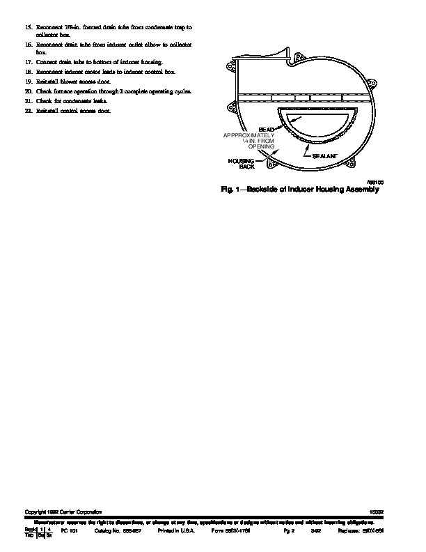
SAFETY CONSIDERATIONS Installation and service of heating equipment can be hazardous due to gas and electrical components. Only trained personnel should install or service heating equipment. Untrained personnel can perform basic maintenance functions such as cleaning coils, or cleaning and replacing filters. All other operations should be performed by trained service personnel. When working on heating equipment, observe precautions in literature, and on tags and labels attached to the unit. Follow all safety codes. Wear safety glasses and work gloves. Have a fire extinguisher available. 7. Remove 2 screws securing vent enclosure and remove enclosure. 8. Loosen hose clamp at vent pipe connection; disconnect vent pipe. Position vent pipe out of way. 9. Remove and discard mounting screws securing inducer assembly (motor and housing). Remove inducer assembly from furnace. The removal of the inducer assembly from the unit will require some amount of force to break the RTV sealant between the housing back and the collector box. 10. Loosen rectangular clamp on outlet elbow which secures it to inducer assembly and remove elbow. 11. Remove screw securing top mounting bracket and motor ground wire to cover plate. Save mounting bracket. 12. Lay inducer assembly on flat surface and remove left and right mounting brackets. 13. Remove remaining screws (7) securing motor assembly to inducer housing. Step 2–Installation of New Inducer Housing 1. Carefully clean old sealant from collector box outlet. 2. Lay new inducer housing on flat surface and install new cover plate gasket in groove around front opening. Before beginning any installation or modification, be sure the main electrical disconnect switch is in the OFF position. Electrical shock can cause personal injury or death. DESCRIPTION AND USAGE The Inducer Housing Kit is designed for use when replacement of the factory-installed inducer housing is required. The kit contains the following items: Inducer housing Cover plate gasket Stainless screws Screws for plastic (wide pitch threads) Installation Instruction INSTALLATION Step 1–Removal of Inducer Assembly 1. Turn OFF gas and electrical supplies to unit. 2. Remove control and blower access doors. 3. Loosen hose clamp (at collector box) on drain tube from inducer outlet elbow. Remove tube from collector box. 4. Disconnect inducer motor leads. 5. Remove mounting screws securing inducer control box/pressure switch assembly (if used) and position box assembly out of way. 6. Loosen hose clamp and remove drain tube from bottom of inducer housing. (1) (1) (5) (14) (1) 3. Position motor assembly on inducer housing. Ensure cover plate gasket is properly seated in groove. 4. Using wide pitch screws (provided in kit), secure cover plate to inducer housing–leave top hole vacant. 5. Install right and left mounting brackets on inducer housing –use 2 wide pitch screws per bracket. 6. Install top mounting bracket (wide end to cover plate) and motor ground wire on vacant hole at top of housing. 7. Press outlet elbow on inducer housing and tighten rectangular clamp. Do not over tighten. 8. Apply releasing agent to area around outlet opening of collector box. 9. Apply 1/8- to 3/16-in. diameter continuous bead of RTV sealant around inlet opening of inducer housing. Do not allow sealant to set more than 10 minutes before installation. (See Fig. 1.) 10. Position inducer assembly in furnace. 11. Using stainless steel screws (provided in kit), secure inducer assembly to collector box and coupling box. Keep inducer assembly movement to a minimum to avoid spreading sealant. 12. Reconnect vent pipe. 13. Reinstall vent enclosure. 14. Using 2 wide pitch screws, install inducer control box/pressure switch assembly on inducer housing. Manufacturer reserves the right to discontinue, or change at any time, specifications or designs without notice and without incurring obligations. Book 1 4 PC 101 Catalog No. 565-957 Printed in U.S.A. Form 58DX-17SI Pg 1 3-92 Replaces: 58DX-6SI Tab 6a 8a 15. Reconnect 7/8-in. formed drain tube from condensate trap to collector box. 16. Reconnect drain tube from inducer outlet elbow to collector box. 17. Connect drain tube to bottom of inducer housing. 18. Reconnect inducer motor leads to inducer control box. 19. Reinstall blower access door. 20. Check furnace operation through 2 complete operating cycles. 21. Check for condensate leaks. 22. Reinstall control access door. BEAD APPPROXIMATELY 1/4 IN. FROM OPENING HOUSING BACK SEALANT A86100 Fig. 1–Backside of Inducer Housing Assembly 1992 Carrier Corporation 15032 Manufacturer reserves the right to discontinue, or change at any time, specifications or designs without notice and without incurring obligations. Book 1 4 PC 101 Catalog No. 565-957 Printed in U.S.A. Form 58DX-17SI Pg 2 3-92 Replaces: 58DX-6SI Tab 6a 8a …