| Categories | Carrier HVAC Manuals |
|---|---|
| Document Type | Heating, Ventilating and Air Conditioning Manual Free Download. HAVC Operator's Instruction Manual. |
| Tags | Carrier 58DX |
| Download File |
|
| Language | English |
| Product Brand | Carrier. Support Phone Number: In North America, please call 1-800-CARRIER for immediate customer assistance from 8:00a -5:00p (EST) weekdays , Heating, Ventilating and Air Conditioning - HVAC |
| Document File Type | |
| Publisher | corp.carrier.com |
| Wikipedia's Page | Carrier Corporation |
| Copyright | Attribution Non-commercial |
Intake Coupling Box Assembly Cancels: AR1100003A IIK 399A-40-6 3-1-92 Installation Instructions Part No. 319344-751 through -754 NOTE: Read the entire instruction before starting the installation. INTRODUCTION This instruction covers installation of an Intake Coupling Box Assembly, Part No. 310841-751, -752, and -753 in a downflow condensing furnace. NOTE: A releasing agent (Pam cooking spray or equivalent) and RTV sealant (G.E.
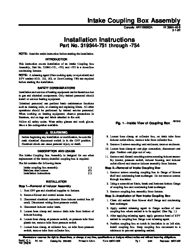
122, 162, or Dow-Corning 738) are required before starting the installation. SAFETY CONSIDERATIONS Installation and service of heating equipment can be hazardous due to gas and electrical components. Only trained personnel should install or service heating equipment. Untrained personnel can perform basic maintenance functions such as cleaning coils, or cleaning and replacing filters. All other operations should be performed by trained service personnel. When working on heating equipment, observe precautions in literature, and on tags and labels attached to the unit. Follow all safety codes. Wear safety glasses and work gloves. Have a fire extinguisher available. Fig. 1–Inside View of Coupling Box A87318 Before beginning any installation or modification, be sure the main electrical disconnect switch is in the OFF position. Electrical shock can cause personal injury or death. DESCRIPTION AND USAGE The Intake Coupling Box Assembly is designed for use when replacement of the factory-installed coupling box is required. The kit contains the following items: Intake coupling box assembly Stainless steel screws Installation Instructions INSTALLATION Step 1–Removal of Inducer Assembly 1. Turn OFF gas and electrical supplies to furnace. 2. Remove blower and control access doors. 3. Disconnect electrical connector from inducer control box (if used). Disconnect wiring from pressure switch. 4. Disconnect inducer motor leads. 5. Loosen hose clamp and remove drain tube from bottom of inducer housing. 6. Loosen hose clamp, at pressure switch, on pressure tube from plastic tee; remove tube from pressure switch. 7. Loosen hose clamp, at collector box, on tube from pressure switch; remove tube from collector box. (1) (5) (1) 8. Loosen hose clamp, at collector box, on drain tube from inducer outlet elbow; remove tube from collector box. 9. Remove 2 screws securing vent enclosure; remove enclosure. 10. Loosen hose clamp at vent pipe connection; disconnect vent pipe. Position vent pipe out of way. 11. Remove and discard mounting screws securing inducer assembly (motor, pressure switch, inducer housing, and inducer outlet elbow) and remove inducer assembly from furnace. Step 2–Removal of Intake Coupling Box 1. Remove screws securing coupling box to flange of blower shelf and condensing heat exchanger. Do not remove screws through insulation. 2. Using a screwdriver blade, break seal between bottom flange of coupling box and condensing heat exchanger. 3. Remove coupling box assembly from furnace. Step 3–Installation of New Intake Coupling Box 1. Clean old sealant from blower shelf flange and condensing heat exchanger. 2. Apply sealant releasing agent to flange surface of new coupling box where sealant is to be applied. (See Fig. 1.) 3. After applying releasing agent, apply generous bead of RTV sealant to coupling box flange over releasing agent. 4. Position coupling box so notch in insulation is on left side; install coupling box. Keep coupling box movement to a minimum to prevent spreading sealant. Manufacturer reserves the right to discontinue, or change at any time, specifications or designs without notice and without incurring obligations. Book 1 4 PC 101 Catalog No. 565-960 Printed in U.S.A. Form 58DX-18SI Pg 1 3-92 Replaces: 58DX-3SI Tab 6a 8a Step 4–Reinstall Inducer Assembly