| Categories | Carrier HVAC Manuals |
|---|---|
| Document Type | Heating, Ventilating and Air Conditioning Manual Free Download. HAVC Operator's Instruction Manual. |
| Tags | Carrier 58M |
| Download File |
|
| Language | English |
| Product Brand | Carrier. Support Phone Number: In North America, please call 1-800-CARRIER for immediate customer assistance from 8:00a -5:00p (EST) weekdays , Heating, Ventilating and Air Conditioning - HVAC |
| Document File Type | |
| Publisher | corp.carrier.com |
| Wikipedia's Page | Carrier Corporation |
| Copyright | Attribution Non-commercial |
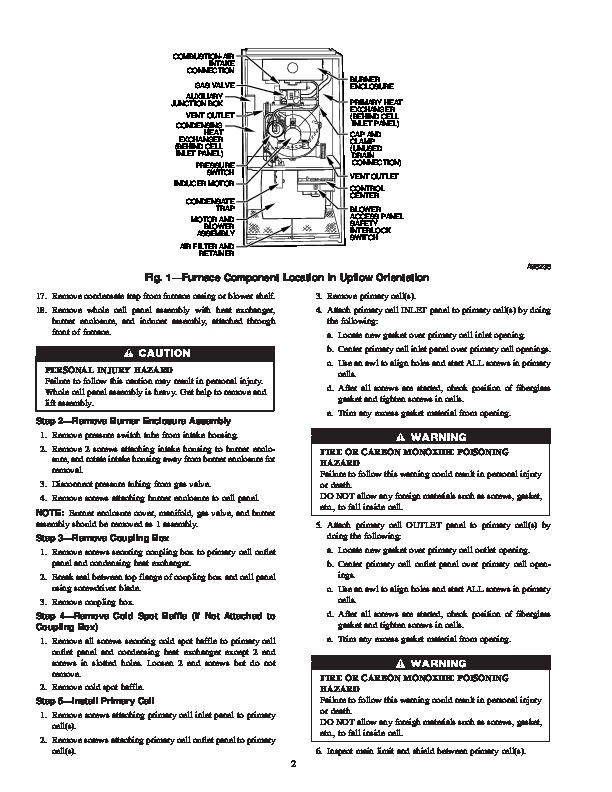
Primary Cell Kit Cancels: IIK 340M-40-66 IIK 340M-40-94 8-05 Installation Instructions Part No. 320723-751 NOTE: Read the entire instruction manual before starting the installation. This symbol indicates a change since the last issue. SAFETY CONSIDERATIONS Installing and servicing of heating equipment can be hazardous due to gas and electrical components. Only trained personnel should install or service heating equipment.
Heating, Ventilating and Air Conditioning User Manual Free Download. HAVC Operator’s Manual. Gas Furnace and AC Free Instruction Manual Download PDF.
Untrained personnel can perform basic maintenance functions such as cleaning and replacing filters. All other operations should be performed by trained service personnel. When working on heating equipment, observe precautions in the literature, on tags, and on labels attached to the unit. Follow all safety codes. Wear safety glasses and work gloves. Have a fire extinguisher available. Recognize safety information. This is the safety-alert symbol. When you see this symbol on the furnace and in instructions or manuals, be alert to the potential for personal injury. Understand the signal words DANGER, WARNING, and CAUTION. These words are used with the safety-alert symbol. DANGER identifies the most serious hazards which will result in severe personal injury or death. WARNING signifies a hazard which could result in personal injury or death. CAUTION is used to identify unsafe practices which may result in minor personal injury or product and property damage. NOTE is used to highlight suggestions which will result in enhanced installation, reliability, or operation. DESCRIPTION AND USAGE Use this primary cell kit when replacement of factory-installed primary cell(s) is required. This primary cell kit contains the following items: Primary cell Cell inlet opening gasket Cell outlet opening gasket Screw (No. 8D X 3/8-in. LG) Installation Instructions INSTALLATION Step 1–Remove Complete Cell Panel Assembly See Fig. 1 for furnace component location. See Fig. 2 for exploded view of heat system components. 1. Turn off gas and electrical supplies to furnace. 2. Remove furnace door. 3. Remove blower access panel. 4. Disconnect field power supply wires from J-box. 5. Remove 2 screws securing J-box. 6. Disconnect combustion-air intake pipe from intake housing. Move pipe out of furnace casing. 7. Disconnect vent pipe from inducer housing by loosening coupling clamp on vent pipe. Move pipe out of furnace casing. 8. Disconnect gas supply pipe from gas valve using backup wrench. 9. Remove 2 screws securing top filler panel and rotate panel upwards to remove or allow the heat exchanger to be removed from front of furnace. 10. Remove inducer motor leads, pressure switch, flame sensor, hot surface ignitor, gas valve, and limit switch wires and remove harness from blower shelf. Allow harness and J-box to hang below blower shelf. 11. Remove 2 screws securing blower to blower shelf. 12. Remove 2 screws (next to blower mounting screws) securing blower shelf to cell panel. 13. Remove 3 screws from each side of cell panel through front of furnace opening. 14. Remove control center by removing screw and pressing tabs inward when control center is mounted on furnace casing side. 15. Disconnect field drain connection from condensate trap. 16. Disconnect drain and relief port tube from condensate trap. 9 1 FIRE, EXPLOSION AND SHOCK HAZARD Failure to follow this warning could result in personal injury or death. Turn off gas and electrical supplies to unit before beginning any installation or modification. Follow operating instructions on label attached to furnace. INTRODUCTION This instruction covers installation of the primary cell kit Part No. 320723-751 in 40-in. tall, condensing gas furnaces. NOTE: A releasing agent such as PAM cooking spray or equivalent (must not contain corn or canola oil, halogenated hydrocarbons nor aromatic content, to prevent inadequate sealing) and RTV sealant (G.E. 162 or Dow-Corning 738) are needed before starting installation. DO NOT substitute any other type of RTV sealant. Manufacturer reserves the right to discontinue, or change at any time, specifications or designs without notice and without incurring obligations. Book 1 4 PC 101 Printed in U.S.A. Pg 1 8-05 Tab 6a 8a COMBUSTION-AIR INTAKE CONNECTION GAS VALVE AUXILIARY JUNCTION BOX VENT OUTLET CONDENSING HEAT EXCHANGER (BEHIND CELL INLET PANEL) PRESSURE SWITCH INDUCER MOTOR CONDENSATE TRAP MOTOR AND BLOWER ASSEMBLY AIR FILTER AND RETAINER A96236 BURNER ENCLOSURE PRIMARY HEAT EXCHANGER (BEHIND CELL INLET PANEL) CAP AND CLAMP (UNUSED DRAIN CONNECTION) VENT OUTLET CONTROL CENTER BLOWER ACCESS PANEL SAFETY INTERLOCK SWITCH Fig. 1.