| Categories | Carrier HVAC Manuals |
|---|---|
| Document Type | Heating, Ventilating and Air Conditioning Manual Free Download. HAVC Operator's Instruction Manual. |
| Tags | Carrier 58M |
| Download File |
|
| Language | English |
| Product Brand | Carrier. Support Phone Number: In North America, please call 1-800-CARRIER for immediate customer assistance from 8:00a -5:00p (EST) weekdays , Heating, Ventilating and Air Conditioning - HVAC |
| Document File Type | |
| Publisher | corp.carrier.com |
| Wikipedia's Page | Carrier Corporation |
| Copyright | Attribution Non-commercial |
PSC Inducer Motor Housing Assembly Kit Cancels: IIK 340M-40-13 IIK 340M-40-15 6-96 Installation Instructions Part No. 320725-753 NOTE: Read the entire instruction manual before starting the installation. This symbol indicates a change since the last issue. SAFETY CONSIDERATIONS Installing and serving of heating equipment can be hazardous due to gas and electrical components. Only trained personnel should install or service heating equipment.
Heating, Ventilating and Air Conditioning User Manual Free Download. HAVC Operator’s Manual. Gas Furnace and AC Free Instruction Manual Download PDF.
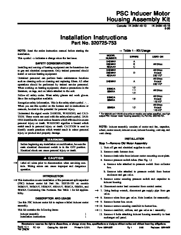
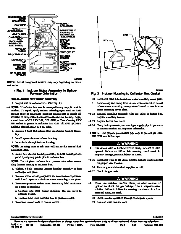
Untrained personnel can perform basic maintenance functions such as cleaning coils or cleaning and replacing filters. All other operations should be performed by trained service personnel. When working on heating equipment, observe precautions in the literature, on tags, and on labels attached to the unit. Follow all safety codes. Wear safety glasses and work gloves. Have fire extinguisher available Recognize safety information. This is the safety-alert symbol When you see this symbol on the furnace and in instructions or manuals, be alert to the potential for personal injury. Understand the signal words DANGER, WARNING, and CAUTION. These words are used with the safety-alert symbol. DANGER identifies the most serious hazards which will result in severe personal injury or death. WARNING signifies a hazard which could result in personal injury or death. CAUTION is used to identify unsafe practices which would result in minor personal injury or product and property damage. Table 1–Kit Usage MODEL NUMBER 340MAV 350MAV 490AAV 340MAV 350MAV 490AAV 345MAV 58MCA 58MXA 58MCA 58MXA 58MSA SERIES A B C D USED ON All Sizes All Sizes Except 060120* All Sizes Except 060120* All Sizes All Sizes Except 120-20* All Sizes Except 120-20* A 101 111 121 131 101 * For 060120 and 120-20 size units on models and series specified, use high output PSC inducer motor housing assembly kit, Part No. 320725-754. NOTE: Inducer assembly consists of motor and fan, capacitor, wheel, motor mount, inducer cover, inducer housing, vent cap, and vent clamp. INSTALLATION Before beginning any installation or modification, be sure the main electrical disconnect switch is in the OFF position. Electrical shock can cause personal injury or death. Step 1–Remove Old Motor Assembly 1. Turn off gas and electrical supplies to unit. 2. Remove main furnace door. 3. Remove drain tube from inducer motor mounting cover plate. 4. Remove pressure switch tubes. (See Fig. 1.) Label all wires prior to disconnection when servicing controls. Wiring errors can cause improper and dangerous operation. INTRODUCTION a. Remove tube attached to pressure switch from collector box. b. Remove tube attached to pressure switch from burner enclosure and gas valve. 5. Remove screw securing pressure switch and capacitor to inducer housing. This instruction covers installation of the permanent split capacitor (PSC) inducer motor kit Part No. 320725-753 on models 340MAV, 345MAV, 350MAV, 490AAV, 58MCA, 58MSA, and 58MXA Condensing Gas Furnaces. See Table 1 for kit applicability. DESCRIPTION AND USAGE Use this PSC inducer motor kit to replace a failed inducer motor assembly. This kit contains the following items: Inducer assembly Installation Instructions 1 1 6. Disconnect motor lead connector from control center. 7. Using backup wrench, disconnect gas supply pipe from gas valve. Remove wires from gas valve. Note location for reassembly. Remove burner box cover. Remove screws securing manifold to burner box. Remove manifold, orifices, and gas valve as 1 assembly. 8. 9. 10. 11. 12. Remove 4 bolts attaching inducer housing assembly to heat exchanger cell panel. Manufacturer reserves the right to discontinue, or change at any time, specifications or designs without notice and without incurring obligations. Book 1 4 PC 101 Catalog No. 535-812 Printed in U.S.A. Form 58M-30SI Pg 1 6-96 Replaces: 58M-29SI Tab 6a 8a COMBUSTION-AIR INTAKE CONNECTION GAS VALVE AUXILIARY JUNCTION BOX VENT OUTLET CONDENSING HEAT EXCHANGER (BEHIND CELL INLET PANEL) PRESSURE SWITCH INDUCER MOTOR CONDENSATE TRAP MOTOR AND BLOWER ASSEMBLY AIR FILTER AND RETAINER A96236 BURNER ENCLOSURE PRIMARY HEAT EXCHANGER (BEHIND CELL INLET PANEL) CAP AND CLAMP (UNUSED DRAIN CONNECTION) VENT OUTLET CONTROL CENTER BLOWER ACCESS PANEL SAFETY INTERLOCK SWITCH PAM RTV NOTE: Actual component location may vary depending on model and series.