| Categories | Carrier HVAC Manuals |
|---|---|
| Document Type | Heating, Ventilating and Air Conditioning Manual Free Download. HAVC Operator's Instruction Manual. |
| Tags | Carrier 58M |
| Download File |
|
| Language | English |
| Product Brand | Carrier. Support Phone Number: In North America, please call 1-800-CARRIER for immediate customer assistance from 8:00a -5:00p (EST) weekdays , Heating, Ventilating and Air Conditioning - HVAC |
| Document File Type | |
| Publisher | corp.carrier.com |
| Wikipedia's Page | Carrier Corporation |
| Copyright | Attribution Non-commercial |
ICM Inducer Motor Assembly Kit Cancels: IIK 355M-40-5 IIK 355M-40-6 3-00 Installation Instructions Part No. 320727-755 NOTE: Read the entire instruction manual before starting the installation. This symbol indicates a change since the last issue. SAFETY CONSIDERATIONS Installing and servicing of heating equipment can be hazardous due to gas and electrical components. Only trained personnel should install or service heating equipment.
Heating, Ventilating and Air Conditioning User Manual Free Download. HAVC Operator’s Manual. Gas Furnace and AC Free Instruction Manual Download PDF.
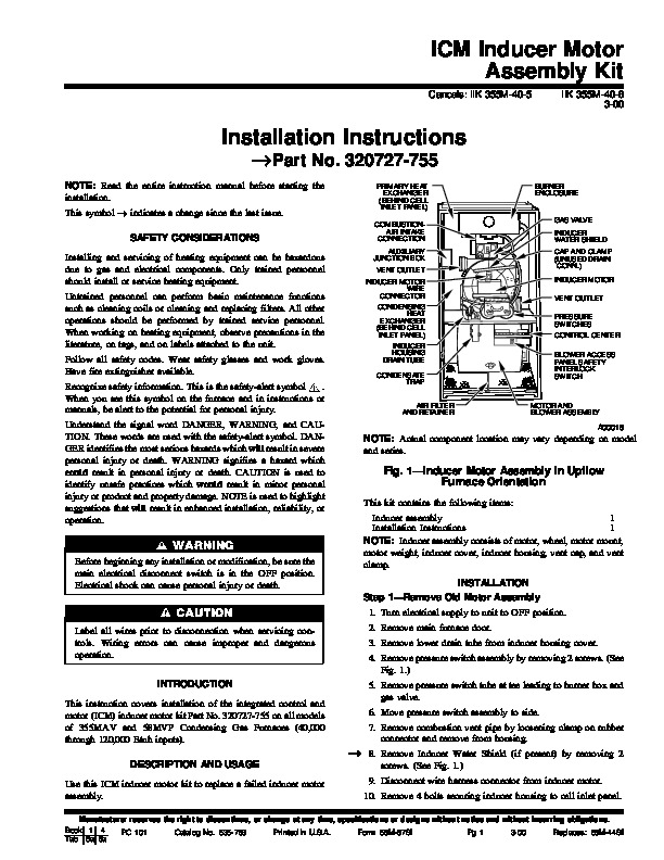
Untrained personnel can perform basic maintenance functions such as cleaning coils or cleaning and replacing filters. All other operations should be performed by trained service personnel. When working on heating equipment, observe precautions in the literature, on tags, and on labels attached to the unit. Follow all safety codes. Wear safety glasses and work gloves. Have fire extinguisher available. Recognize safety information. This is the safety-alert symbol. When you see this symbol on the furnace and in instructions or manuals, be alert to the potential for personal injury. Understand the signal word DANGER, WARNING, and CAUTION. These words are used with the safety-alert symbol. DANGER identifies the most serious hazards which will result in severe personal injury or death. WARNING signifies a hazard which could result in personal injury or death. CAUTION is used to identify unsafe practices which would result in minor personal injury or product and property damage. NOTE is used to highlight suggestions that will result in enhanced installation, reliability, or operation. PRIMARY HEAT EXCHANGER (BEHIND CELL INLET PANEL) COMBUSTIONAIR INTAKE CONNECTION AUXILIARY JUNCTION BOX VENT OUTLET INDUCER MOTOR WIRE CONNECTOR CONDENSING HEAT EXCHANGER (BEHIND CELL INLET PANEL) INDUCER HOUSING DRAIN TUBE CONDENSATE TRAP AIR FILTER AND RETAINER BURNER ENCLOSURE GAS VALVE INDUCER WATER SHIELD CAP AND CLAMP (UNUSED DRAIN CONN.) INDUCER MOTOR VENT OUTLET PRESSURE SWITCHES CONTROL CENTER BLOWER ACCESS PANEL SAFETY INTERLOCK SWITCH MOTOR AND BLOWER ASSEMBLY A00018 NOTE: Actual component location may vary depending on model and series. Fig. 1–Inducer Motor Assembly in Upflow Furnace Orientation This kit contains the following items: Inducer assembly 1 Installation Instructions 1 NOTE: Inducer assembly consists of motor, wheel, motor mount, motor weight, inducer cover, inducer housing, vent cap, and vent clamp. INSTALLATION Step 1–Remove Old Motor Assembly 1. Turn electrical supply to unit to OFF position. 2. Remove main furnace door. 3. Remove lower drain tube from inducer housing cover. 4. Remove pressure switch assembly by removing 2 screws. (See Fig. 1.) 5. Remove pressure switch tube at tee leading to burner box and gas valve. 6. Move pressure switch assembly to side. 7. Remove combustion vent pipe by loosening clamp on rubber connector and remove from housing. 8. Remove Inducer Water Shield (if present) by removing 2 screws. (See Fig. 1.) 9. Disconnect wire harness connector from inducer motor. 10. Remove 4 bolts securing inducer housing to cell inlet panel. Before beginning any installation or modification, be sure the main electrical disconnect switch is in the OFF position. Electrical shock can cause personal injury or death. Label all wires prior to disconnection when servicing controls. Wiring errors can cause improper and dangerous operation. INTRODUCTION This instruction covers installation of the integrated control and motor (ICM) inducer motor kit Part No. 320727-755 on all models of 355MAV and 58MVP Condensing Gas Furnaces (40,000 through 120,000 Btuh inputs). DESCRIPTION AND USAGE Use this ICM inducer motor kit to replace a failed inducer motor assembly.