
| Categories | Carrier HVAC Manuals |
|---|---|
| Document Type | Heating, Ventilating and Air Conditioning Manual Free Download. HAVC Operator's Instruction Manual. |
| Tags | Carrier 58M |
| Download File |
|
| Language | English |
| Product Brand | Carrier. Support Phone Number: In North America, please call 1-800-CARRIER for immediate customer assistance from 8:00a -5:00p (EST) weekdays , Heating, Ventilating and Air Conditioning - HVAC |
| Document File Type | |
| Publisher | corp.carrier.com |
| Wikipedia's Page | Carrier Corporation |
| Copyright | Attribution Non-commercial |
Ignitor Bracket Kit Cancels: New IIK 340M-40-73 7-00 Installation Instructions Part No. 326167751 NOTE: Read the entire instruction manual before starting the installation. SAFETY CONSIDERATIONS Installing and servicing of heating equipment can be hazardous due to gas and electrical components. Only trained personnel should install or service heating equipment. Untrained personnel can perform basic maintenance functions such as cleaning coils or cleaning and replacing filters.
Heating, Ventilating and Air Conditioning User Manual Free Download. HAVC Operator’s Manual. Gas Furnace and AC Free Instruction Manual Download PDF.
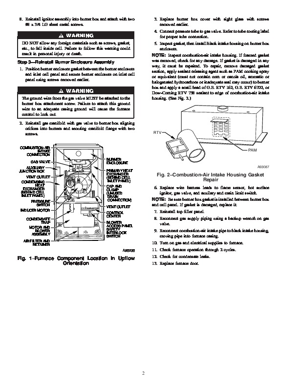
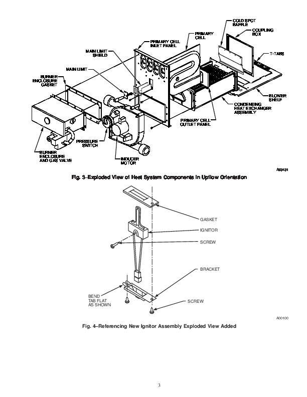
All other operations should be performed by trained service personnel. When working on heating equipment, observe precautions in the literature, on tags, and on labels attached to the unit. Follow all safety codes. Wear safety glasses and work gloves. Have a fire extinguisher available. Recognize safety information. This is the safety-alert symbol. When you see this symbol on the furnace and in instructions or manuals, be alert to the potential for personal injury. Understand the signal words, DANGER, WARNING, and CAUTION. These words are used with the safety-alert symbol. DANGER identifies the most serious hazards which will result in severe personal injury or death. WARNING signifies a hazard whichcould result in personal injury or death. CAUTION is used to identify unsafe practices which would result in minor personal injury or product and property damage. NOTE is used to highlight suggestions which will result in enhanced installation, reliability, or operation. INSTALLATION Step 1–Remove Complete Burner Box Assembly NOTE: Instructions written for upflow orientation. Some modifications may be required for other orientations. See Fig. 1 for furnace component locations. See Fig. 3 for exploded view of heat system components. 1. Turn off gas and electrical supplies to furnace. 2. Remove furnace door. 3. Disconnect combustion-air intake pipe from intake housing. Move pipe out of furnace casing. 4. Disconnect gas supply pipe from gas valve using backup wrench. 5. Remove 2 screws securing top filler panel and rotate panel upwards to remove. 6. Remove flame sensor leads, hot surface ignitor, gas valve, auxilary and main limit switch wires and lay harness on blower shelf. Identify wires for proper reconnection. 7. Remove 2 screws securing black plastic air intake housing to burner enclosure, and rotate intake housing away from burner enclosure for removal. 8. Remove pressure switch tube from intake housing. 9. Remove screws securing burner box cover with sight glass. 10. Remove screws securing gas manifold to burner box removing from burner box. 11. Remove screws in burner box flange to remove burner box and gasket assembly from center cell panel. Step 2–Install Ignitor 1. Remove original ignitor bracket with ignitor. 2. Modify new ignitor bracket (supplied in this kit). Bend 3/8 inch angled tab flat to match horizontal surface of bracket that mounts flush to the burner box. (See Fig. 4) 3. Install ignitor in bracket passing ignitor molex plug and wire leads through bracket and gasket. Rest ignitor in bracket. 4. Attach ignitor to bracket using one #8 x 3/4 LG screw. NOTE: Do not overtighten screw or ceramic may break. 5. Insert ignitor assembly into burner box ignitor hole. Turn off gas and electrical supplies to unit before beginning any installation or modification. Follow operating instructions on label attached to furnace. Failure to follow this warning could result in personal injury or death. INTRODUCTION This instruction covers installation of the ignitor bracket kit Part No. 326167751 in 40in. tall, condensing gas furnaces.