| Categories | Carrier HVAC Manuals |
|---|---|
| Document Type | Heating, Ventilating and Air Conditioning Manual Free Download. HAVC Operator's Instruction Manual. |
| Tags | Carrier 58M |
| Download File |
|
| Language | English |
| Product Brand | Carrier. Support Phone Number: In North America, please call 1-800-CARRIER for immediate customer assistance from 8:00a -5:00p (EST) weekdays , Heating, Ventilating and Air Conditioning - HVAC |
| Document File Type | |
| Publisher | corp.carrier.com |
| Wikipedia's Page | Carrier Corporation |
| Copyright | Attribution Non-commercial |
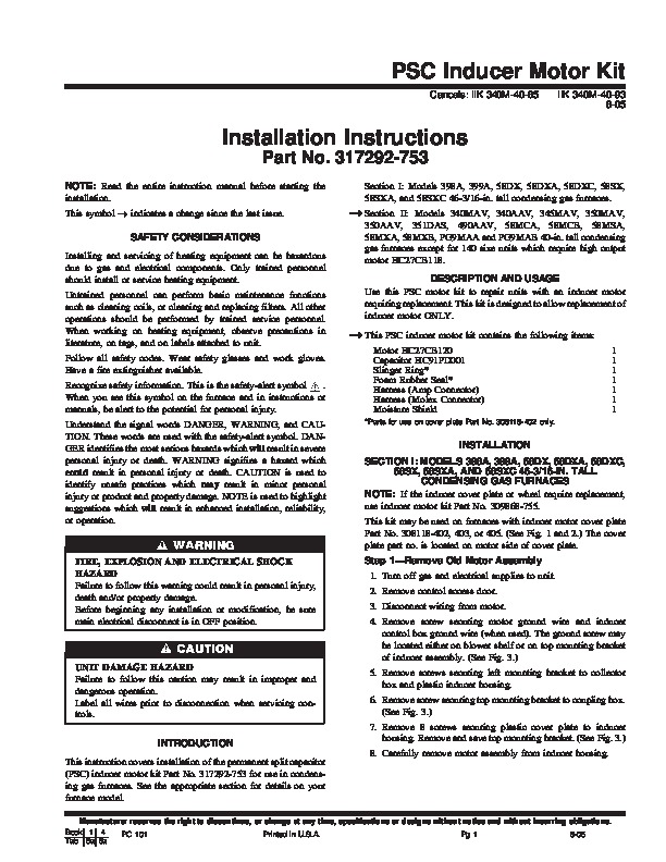
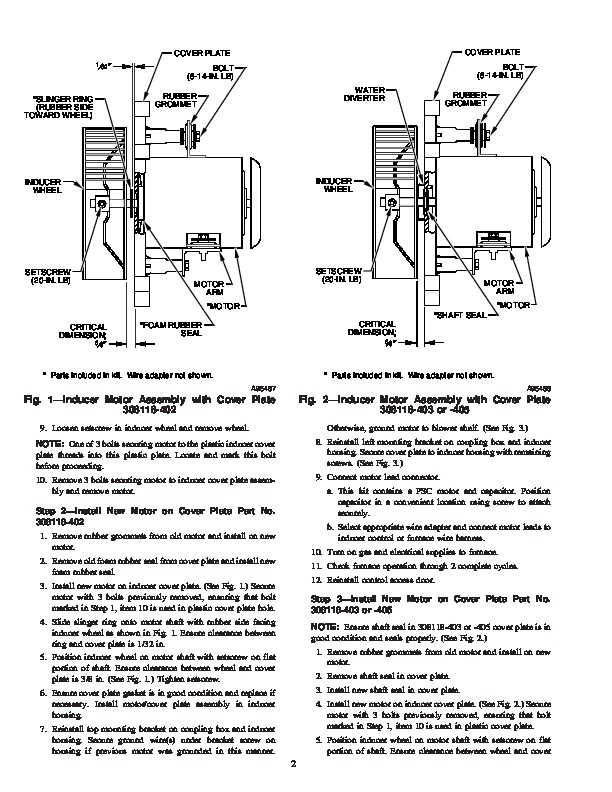
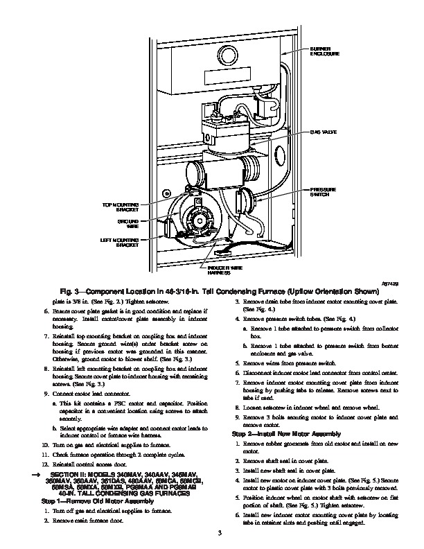
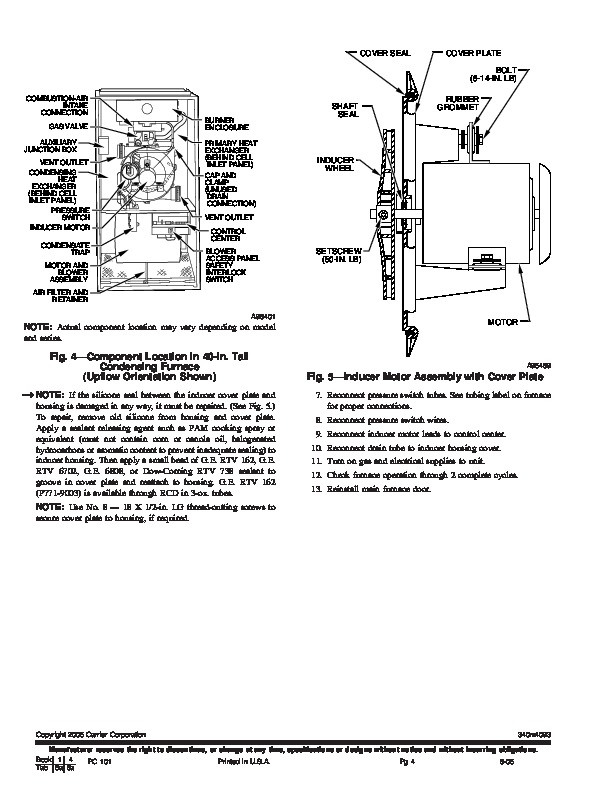
PSC Inducer Motor Kit Cancels: IIK 340M-40-65 IIK 340M-40-93 8-05 Installation Instructions Part No. 317292-753 NOTE: Read the entire instruction manual before starting the installation. This symbol indicates a change since the last issue. SAFETY CONSIDERATIONS Installing and servicing of heating equipment can be hazardous due to gas and electrical components. Only trained personnel should install or service heating equipment.
Untrained personnel can perform basic maintenance functions such as cleaning coils, or cleaning and replacing filters. All other operations should be performed by trained service personnel. When working on heating equipment, observe precautions in literature, on tags, and on labels attached to unit. Follow all safety codes. Wear safety glasses and work gloves. Have a fire extinguisher available Recognize safety information. This is the safety-alert symbol When you see this symbol on the furnace and in instructions or manuals, be alert to the potential for personal injury. Understand the signal words DANGER, WARNING, and CAUTION. These words are used with the safety-alert symbol. DANGER identifies the most serious hazards which will result in severe personal injury or death. WARNING signifies a hazard which could result in personal injury or death. CAUTION is used to identify unsafe practices which may result in minor personal injury or product and property damage. NOTE is used to highlight suggestions which will result in enhanced installation, reliability, or operation. Section I: Models 398A, 399A, 58DX, 58DXA, 58DXC, 58SX, 58SXA, and 58SXC 46-3/16-in. tall condensing gas furnaces. Section II: Models 340MAV, 340AAV, 345MAV, 350MAV, 350AAV, 351DAS, 490AAV, 58MCA, 58MCB, 58MSA, 58MXA, 58MXB, PG9MAA and PG9MAB 40-in. tall condensing gas furnaces except for 140 size units which require high output motor HC27CB118. DESCRIPTION AND USAGE Use this PSC motor kit to repair units with an inducer motor requiring replacement. This kit is designed to allow replacement of inducer motor ONLY. This PSC inducer motor kit contains the following items: Motor HC27CB120 Capacitor HC91PD001 Slinger Ring* Foam Rubber Seal* Harness (Amp Connector) Harness (Molex Connector) Moisture Shield *Parts for use on cover plate Part No. 308118-402 only. 1 INSTALLATION SECTION I: MODELS 398A, 399A, 58DX, 58DXA, 58DXC, 58SX, 58SXA, AND 58SXC 46-3/16-IN. TALL CONDENSING GAS FURNACES NOTE: If the inducer cover plate or wheel require replacement, use inducer motor kit Part No. 309868-755. This kit may be used on furnaces with inducer motor cover plate Part No. 308118-402, 403, or 405. (See Fig. 1 and 2.) The cover plate part no. is located on motor side of cover plate. Step 1–Remove Old Motor Assembly 1. Turn off gas and electrical supplies to unit. 2. Remove control access door. 3. Disconnect wiring from motor. 4. Remove screw securing motor ground wire and inducer control box ground wire (when used). The ground screw may be located either on blower shelf or on top mounting bracket of inducer assembly. (See Fig. 3.) 5. Remove screws securing left mounting bracket to collector box and plastic inducer housing. 6. Remove screw securing top mounting bracket to coupling box. (See Fig. 3.) 7. Remove 8 screws securing plastic cover plate to inducer housing. Remove and save top mounting bracket. (See Fig. 3.)