
| Categories | Carrier HVAC Manuals |
|---|---|
| Document Type | Heating, Ventilating and Air Conditioning Manual Free Download. HAVC Operator's Instruction Manual. |
| Tags | Carrier 58M |
| Download File |
|
| Language | English |
| Product Brand | Carrier. Support Phone Number: In North America, please call 1-800-CARRIER for immediate customer assistance from 8:00a -5:00p (EST) weekdays , Heating, Ventilating and Air Conditioning - HVAC |
| Document File Type | |
| Publisher | corp.carrier.com |
| Wikipedia's Page | Carrier Corporation |
| Copyright | Attribution Non-commercial |
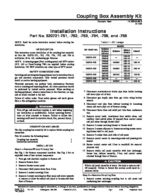
Coupling Box Assembly Kit Cancels: New IIK 350M-35-5 9-1-93 Part No. 320721-751, -752, -753, -754, -755, and -756 NOTE: Read the entire instruction manual before starting the installation. INTRODUCTION This instruction covers installation of the coupling box assembly kit Part No. 320721-751, -752, -753, -754, -755, and -756 in multipoise, 40-in. tall, condensing gas furnaces. NOTE: A releasing agent (Pam cooking spray) and RTV sealant (G.E.
Heating, Ventilating and Air Conditioning User Manual Free Download. HAVC Operator’s Manual. Gas Furnace and AC Free Instruction Manual Download PDF.
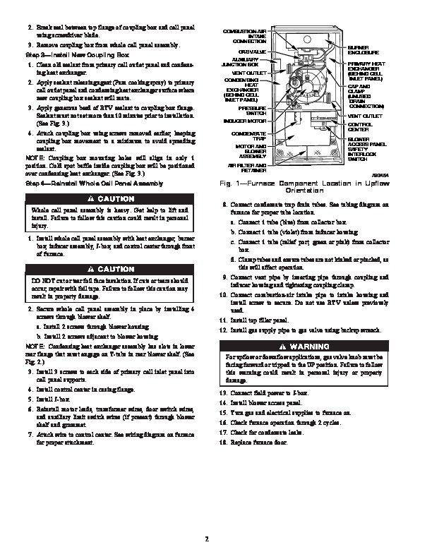
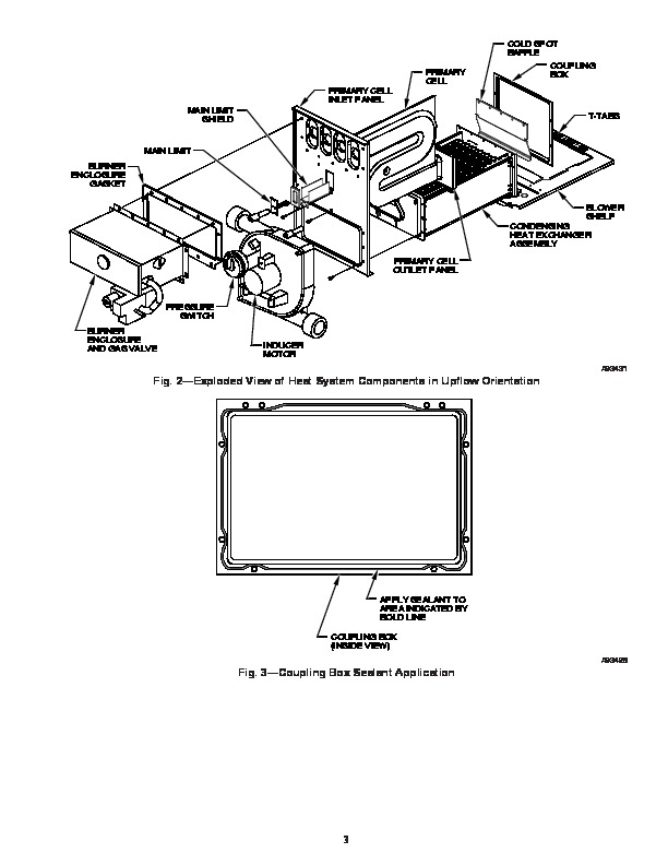
162 or Dow-Corning 738) are required before starting installation. DO NOT substitute any other type of RTV sealant. SAFETY CONSIDERATIONS Installing and servicing heating equipment can be hazardous due to gas and electrical components. Only trained personnel should install or service heating equipment. Untrained personnel can perform basic maintenance functions such as cleaning and replacing filters. All other operations should be performed by trained service personnel. When working on heating equipment, observe precautions in the literature, on tags, and on labels attached to the unit. Follow all safety codes. Wear safety glasses and work gloves. Have a fire extinguisher available. KIT PART NO. Installation Instructions Table 1–Kit Usage MODEL 340MAV 350MAV 490AAV 024040 036040 036060 048060 036080 048080 060080 048100 060100 060120 — 355MAV — 042060 042080 060100 — 042040 58MCA 58MXA 040-08 040-12 060-12 060-16 080-12 080-16 080-20 100-16 100-20 120-20 — 58MVP — 060-14 080-14 100-20 — 040-14 320721-751 320721-752 320721-753 320721-754 320721-755 320721-756 7. Disconnect combustion-air intake pipe from intake housing and move pipe out of way. 8. Disconnect gas supply pipe from gas valve using backup wrench. 9. Disconnect vent pipe from inducer housing by loosening clamp and move pipe out of furnace casing. Turn off gas and electrical supplies to unit before beginning any installation or modification. Follow operating instructions on label attached to furnace. Failure to follow this warning could result in electrical shock, fire, personal injury, or death. DESCRIPTION AND USAGE Use this coupling box assembly kit to replace failed coupling box assemblies. This kit contains the following items: Coupling box assembly Installation Instructions INSTALLATION Step 1–Remove Whole Primary Cell See Fig. 1 for furnace component locations. See Fig. 2 for an exploded view of heat system components. 1. Turn gas and electrical supplies to furnace off. 2. Remove furnace door. 3. Remove blower access panel. 4. Disconnect field power wires from J-box. 5. Remove 2 screws securing J-box. 6. Remove 2 screws securing top filler panel and rotate upwards to remove or allow the whole cell panel to be removed from front of furnace. 0. Disconnect drain tubes and relief port tube from condensate trap. 11. Remove motor leads, transformer door switch wires, and auxiliary limit switch wires (if present) from control center and pull wires through blower shelf. 12. Remove 2 screws securing blower to blower shelf. 13. Remove 2 screws adjacent to blower mounting screws securing blower shelf to cell panel. 14. Remove 3 screws from each side of cell panel. 15. Remove control center by removing screw and pressing tabs inward. 16. Secure control center and J-box to manifold for removal purposes only. 17. Remove whole cell panel assembly with heat exchanger, burner box, inducer assembly, J-box, and control center attached through front of furnace. Whole cell panel assembly is heavy. Get help to remove and lift assembly. Failure to follow this caution could result in personal injury. Step 2–Remove Coupling Box 1. Remove screws securing coupling box to cell panel and condensing heat exchanger. Manufacturer reserves the right to discontinue, or change at any time, specifications or designs without notice and without incurring obligations. Book 1 4 PC 101 Catalog No. 535-865 Printed in U.S.A. Form 58M-9SI Pg 1 9-93 Replaces: New Tab 6a 8a 2. Break seal between top flange of coupling box and cell panel using screwdriver blade. 3. Remove coupling box from whole cell panel assembly. Step 3–Install New Coupling Box 1. Clean old sealant from primary cell outlet panel and condensing heat exchanger. 2. Apply sealant releasing agent (Pam cooking spray) to primary cell outlet panel and condensing heat exchanger surface where new coupling box sealant will mate. 3. Apply generous bead of RTV sealant to coupling box flange. Sealant must not set more than 10 minutes prior to installation. (See Fig. 3.)