| Categories | Carrier HVAC Manuals |
|---|---|
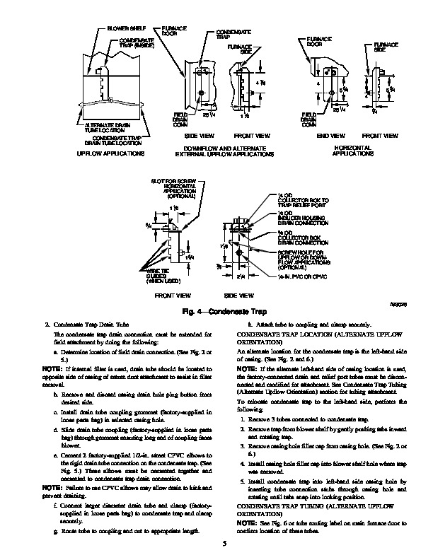
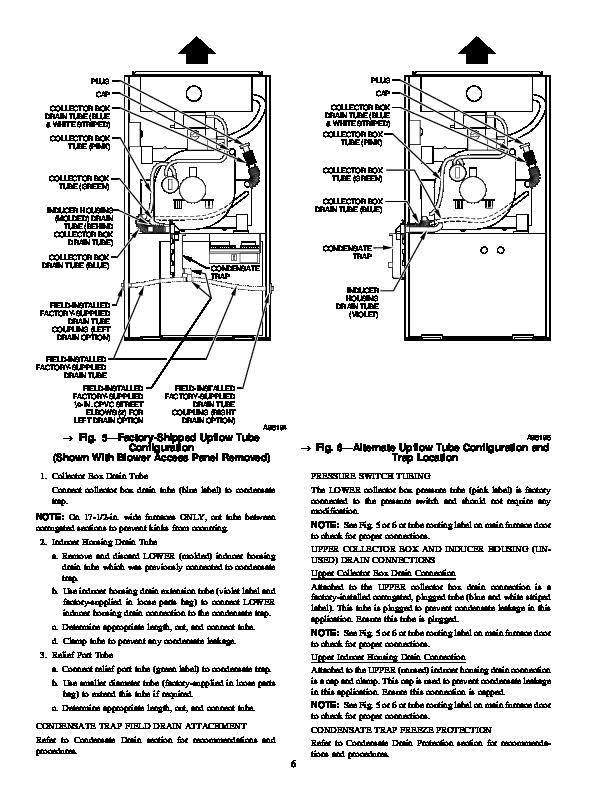
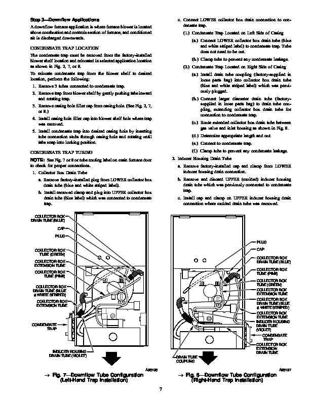
| Document Type | Heating, Ventilating and Air Conditioning Manual Free Download. HAVC Operator's Instruction Manual. |
| Tags | Carrier 58MCA |
| Download File |
|
| Language | English |
| Product Brand | Carrier. Support Phone Number: In North America, please call 1-800-CARRIER for immediate customer assistance from 8:00a -5:00p (EST) weekdays , Heating, Ventilating and Air Conditioning - HVAC |
| Document File Type | |
| Publisher | corp.carrier.com |
| Wikipedia's Page | Carrier Corporation |
| Copyright | Attribution Non-commercial |
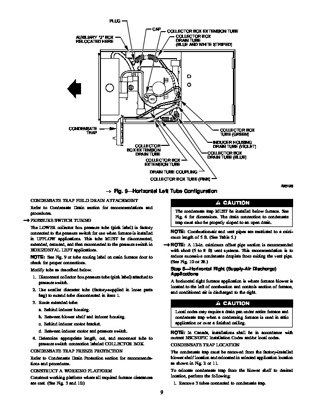
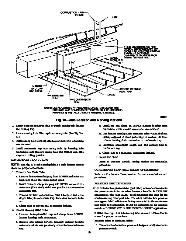
58MCA 4-Way Multipoise Fixed-Capacity Direct-Vent Condensing Gas Furnace Installation, Start-Up, and Operating Instructions For Sizes 040–120, Series 131 ® ama CANADIAN GAS ASSOCIATION A PP R O VED R A93040 NOTE: Read the entire instruction manual before starting the installation. This symbol indicates a change since the last issue. Index Page DIMENSIONAL DRAWING 2 SAFETY CONSIDERATIONS .3 Clearances to Combustibles 3 ELECTROSTATIC DISCHARGE (ESD) PRECAUTIONS 3-4 INTRODUCTION 4 APPLICATIONS 4-11 General 4 Upflow Applications 4-6 Downflow Applications .7-8 Horizontal Left (Supply-Air Discharge) Applications .8-9 Horizontal Right (Supply-Air Discharge) Applications .9-11 LOCATION 11-12 General .11-12 Furnace Location Relative to Cooling Equipment 12 Hazardous Locations .12 INSTALLATION 13-16 Leveling Legs (If Desired) .13 Installation On a Concrete Slab .13 Installation On a Combustible Floor (Downflow Applications) 13-14 Installation In Horizontal Applications 14 Filter Arrangement 15 Bottom Closure Panel .15 Gas Piping .16 ELECTRICAL CONNECTIONS .16-19 115-v Wiring 16-17 24-v Wiring 17-19 Accessories 19 DIRECT VENTING .20-28 Removal of Existing Furnaces from Common Vent Systems .20 Combustion-Air and Vent Piping .20-25 Concentric Vent and Combustion-Air Termination Kit Installation 26-28 Multiventing and Vent Termination .28 CONDENSATE DRAIN 28-30 General 28 Application 28 Condensate Drain Protection .28-30 As an ENERGY STARSM Partner, Carrier Corporation has determined that this product meets the ENERGY STAR guidelines for energy efficiency.
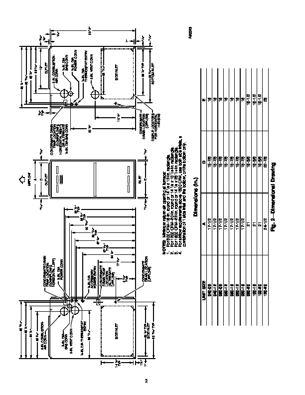
CERTIFICATION OF MANUFACTURING SITE AIRFLOW UPFLOW HORIZONTAL LEFT DOWNFLOW AIRFLOW HORIZONTAL RIGHT AIRFLOW AIRFLOW Fig. 1–Multipoise Orientations A93041 SEQUENCE OF OPERATION 30-31 Heating Mode 30 Cooling Mode .30 Continuous Blower Mode .30-31 Heat Pump Mode 31 Component Test 31 START-UP PROCEDURES 31-37 General .31-32 Prime Condensate Trap With Water 32 Purge Gas Lines 32 Adjustments .32-37 Set Gas Input Rate 32-37 Set Temperature Rise 37 Blower Off Delay (Heat Mode) .37 Set Thermostat Heat Anticipator 37 CHECK SAFETY CONTROLS 37 Check Primary Limit Control .37 Check Pressure Switch .37 CHECKLIST .38-39 Manufacturer reserves the right to discontinue, or change at any time, specifications or designs without notice and without incurring obligations. Book 1 4 PC 101 Catalog No. 565-972 Printed in U.S.A. Form 58MCA-3SI Pg 1 5-96 Replaces: 58MCA-2SI Tab 6a 8a 26 15/16 ” 28 1/2 ” 26 15/16 ” AIRFLOW 26 1/4 ” 22 5/16 ” 13/16 ” 9/16 ” TYP 26 1/4 ” A 13/16 ” 24 1/2 ” D OUTLET 2-IN. COMBUSTIONAIR CONN DIA GAS CONN 7/8-IN. 1/2-IN. 22 19 ” OUTLET CONDENSATE DRAIN TRAP LOCATION (DOWNFLOW & HORIZONTAL LEFT) 7/8-IN. 5/8 ” 5/16 ” 2-IN. COMBUSTIONAIR CONN 13/16 ” DIA GAS CONN 1/2-IN. DIA POWER CONN CONDENSATE DRAIN TRAP LOCATION (DOWNFLOW & HORIZONTAL RIGHT) OR ALTERNATE 1/2-IN. DIA GAS CONN 5/16 ” 2-IN. VENT CONN DIA POWER CONN 1/2-IN. 7/8-IN. DIA THERMOSTAT ENTRY 22 11/16 ” DIA ACCESSORY POWER ENTRY 30 1/2 ” 29 11/16 ” TYP 27 5/8 ” 27 9/16 ” TYP 24 1/2 ” 18 1/4 ” 33 1/4 ” TYP 32 5/8 ” TYP 13/16 ” 30 1/2-IN. DIA THERMOSTAT ENTRY 2-IN. VENT CONN