
| Categories | Carrier HVAC Manuals |
|---|---|
| Document Type | Heating, Ventilating and Air Conditioning Manual Free Download. HAVC Operator's Instruction Manual. |
| Tags | Carrier 58MVP |
| Download File |
|
| Language | English |
| Product Brand | Carrier. Support Phone Number: In North America, please call 1-800-CARRIER for immediate customer assistance from 8:00a -5:00p (EST) weekdays , Heating, Ventilating and Air Conditioning - HVAC |
| Document File Type | |
| Publisher | corp.carrier.com |
| Wikipedia's Page | Carrier Corporation |
| Copyright | Attribution Non-commercial |
ICM Inducer Motor Assembly Kit Cancels: IIK 355M-35-1 IIK 355M-40-2 6-15-94 Installation Instructions Part No. 320727-752 NOTE: Read the entire instruction manual before starting the installation. SAFETY CONSIDERATIONS Installing and servicing of heating equipment can be hazardous due to gas and electrical components. Only trained personnel should install or service heating equipment. Untrained personnel can perform basic maintenance functions such as cleaning coils or cleaning and replacing filters.
Heating, Ventilating and Air Conditioning User Manual Free Download. HAVC Operator’s Manual. Gas Furnace and AC Free Instruction Manual Download PDF.
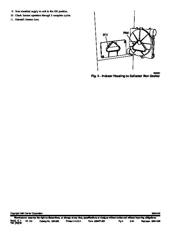
All other operations should be performed by trained service personnel. When working on heating equipment, observe precautions in the literature, on tags, and on labels attached to the unit. Follow all safety codes. Wear safety glasses and work gloves. Have fire extinguisher available Recognize safety information. This is the safety-alert symbol When you see this symbol on the furnace and in instructions or manuals, be alert to the potential for personal injury. Understand the signal words DANGER, WARNING, and CAUTION. These words are used with the safety-alert symbol. DANGER identifies the most serious hazards which will result in severe personal injury or death. WARNING signifies a hazard which could result in personal injury or death. CAUTION is used to identify unsafe practices which would result in minor personal injury or product and property damage. COLLECTOR BOX PRESSURE SWITCHES TUBE INDUCER HOUSING DRAIN A93407 5. Disconnect wire harness connector from inducer motor. 6. Remove 4 bolts securing inducer housing to cell inlet panel. BURNER ENCLOSURE GAS VALVE BURNER ENCLOSURE REFERENCE PRESSURE SWITCH TUBE CAP AND CLAMP (UNUSED DRAIN CONNECTION) CONTROL CENTER INDUCER MOTOR WIRE CONNECTOR PRESSURE SWITCHES Fig. 1–Inducer Motor Assembly in Upflow Furnace Orientation Step 2–Install New Motor Assembly 1. Inspect seal on collector box where new inducer housing will mate to ensure no damage has occurred. (See Fig. 2.) Before beginning any installation or modification, be sure the main electrical disconnect switch is in the OFF position. Electrical shock can cause personal injury or death. INTRODUCTION This instruction covers installation of the integrated control and motor (ICM) inducer motor kit Part No. 320727-752 on models 355MAV and 58MVP Gas-Fired Condensing Furnaces. DESCRIPTION AND USAGE Use this ICM inducer motor kit to replace a failed inducer motor assembly. This kit contains the following items: Inducer assembly (motor, wheel, motor mount, inducer 1 cover, inducer housing, vent cap, and vent clamp) Installation Instructions 1 INSTALLATION Step 1–Remove Old Motor Assembly 1. Turn electrical supply to unit to OFF position. 2. Remove furnace door. 3. Remove drain tube from inducer motor mounting cover plate. 4. Remove pressure switch assembly by removing 2 screws. Secure assembly to motor mount bracket. (See Fig. 1.) NOTE: If collector box seal is damaged in any way, it must be repaired. To repair, apply sealant releasing agent (PAM cooking spray or equivalent, must not contain corn or canola oil, aromatic or halogenated hydrocarbons) to inducer housing. Apply a small bead of GE RTV 162 or Dow-Corning RTV 738 sealant to groove in collector box. 2. Remove 4 mounting spacers from OLD inducer housing and install in new inducer housing. 3. Install NEW inducer housing assembly by reinstalling 4 bolts removed earlier. 4. Secure pressure switch inducer motor mount using 2 screws removed earlier. 5. Reconnect inducer motor wire harness connector. NOTE: See wiring diagram on furnace for proper wire connection. 6. Reconnect drain tube to inducer housing cover. NOTE: See tube routing and connection label on furnace for proper tube location. 7. Remove cap and clamp from unused drain connection on OLD inducer motor mounting cover plate.