| Categories | Carrier HVAC Manuals |
|---|---|
| Document Type | Heating, Ventilating and Air Conditioning Manual Free Download. HAVC Operator's Instruction Manual. |
| Tags | Carrier 58MVP |
| Download File |
|
| Language | English |
| Product Brand | Carrier. Support Phone Number: In North America, please call 1-800-CARRIER for immediate customer assistance from 8:00a -5:00p (EST) weekdays , Heating, Ventilating and Air Conditioning - HVAC |
| Document File Type | |
| Publisher | corp.carrier.com |
| Wikipedia's Page | Carrier Corporation |
| Copyright | Attribution Non-commercial |
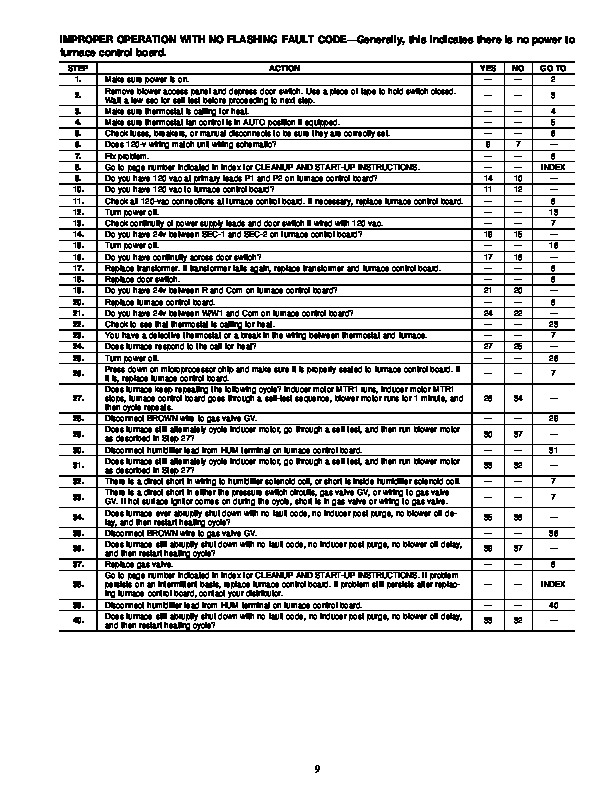
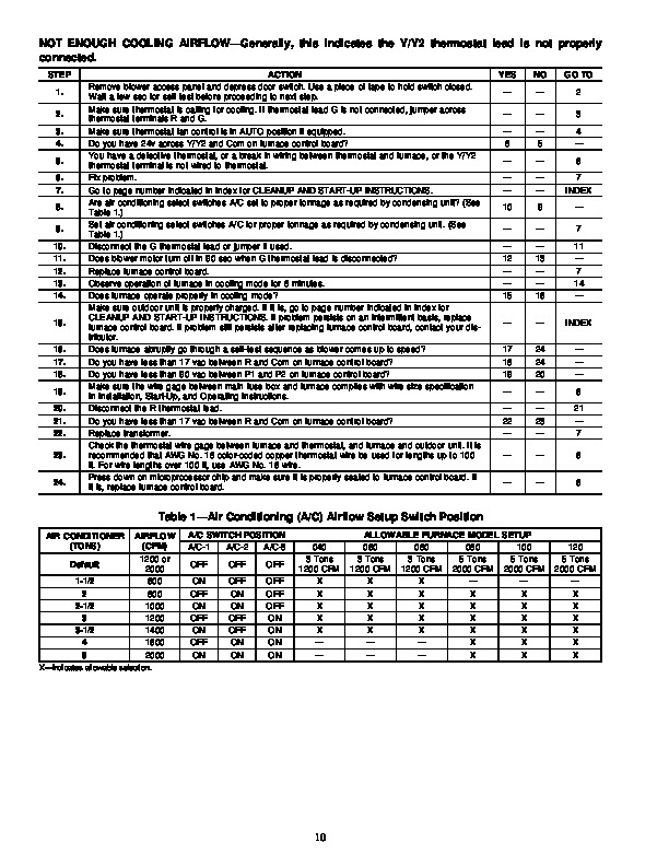
58MVP Variable-Speed 2-Stage Electronic Condensing Furnace Visit www.carrier.com Troubleshooting Guide NOTE: Read the entire instruction manual before starting the installation. SAFETY CONSIDERATIONS INDEX PAGE Instructions .1 Example 2 Sequence of Operation 1-5 Self-Test Mode 2 Heating Mode 2 Heating Mode-Two Stage .2 Emergency Heat Mode 2-3 Cooling Mode .3 Heat Pump Mode .3-4 Continuous Fan Mode 4 Component Test .4-5 Bypass Humidifier Mode 5 Dehumidification Mode 5 Zone Mode 5 Start Here 6 Service Label/Fault Code Instructions .7-8 Improper Operation With No Flashing Fault Code 9 Not Enough Cooling Airflow 10 High-Fire Temperature Rise Too Low (Cold Blow) 11 LEDs 1, 2, 3, or 4 On Solid .11-12 RED LED2 Flashing 12 Fault Code 11–No Fault in Recent History Display 13 Fault Code 12–Blower Calibration Lockout 13-15 Fault Code 13–Limit Switch Lockout 15-16 Fault Code 14–Ignition Lockout 17 Fault Code 21–Invalid Model Selection 17 Fault Code 22–Set Up Error 18 Fault Code 23–Invalid Blower Airflow Selection 18 Fault Code 24–Secondary Voltage Fuse Is Open 19-20 Fault Code 31–High-Pressure Switch Fault .21-22 Fault Code 32–Low-Pressure Switch Fault .23-24 Fault Code 33–Limit Switch Fault .24-25 Fault Code 34–Ignition Proving Fault .26-27 Fault Code 41–Blower Outside Valid Speed Range .27-28 Fault Code 42–Inducer Outside Valid Speed Range .29-30 Fault Code 43–Pressure Switch Calibration Fault .30-31 Fault Code 44–Blower Calibration Fault 32 Cleanup and Start-Up Instructions 33 APPENDIX A–Board Layout & Wiring Schematic .34-35 APPENDIX B–Isolation Circuits 36 APPENDIX C–Pressure Check Diagram 36 APPENDIX D–Quick Motor Test Procedure 37-39 APPENDIX E–Variable-Speed Condensing Furnace Duct Static and Blower Operation .40-44 APPENDIX F–Quick Reference Information .45 APPENDIX G–Thermostat Staging Algorithm .46-47 INSTRUCTIONS This guide uses your expertise and observations to lead you to the trouble spot as efficiently as possible.
This is only intended as a guide and should not be used blindly. Your experience and expertise are of high value when troubleshooting this unit. Do not disregard all of your instincts. The microprocessor furnace control was designed with diagnostic capabilities built in. LEDs are used to flash a fault code which will lead you to 1 of the subsections as listed in the Index. You should ALWAYS begin in the START HERE subsection (see Index for page number) which will guide you to the appropriate subsection where a minimal number of steps will be used to correct the problem. If you are very experienced at how this furnace operates and you suspect the problem is either the blower motor, inducer motor, or furnace control board, you can use the quick motor test procedure at the end of the troubleshooting guide to isolate the problem or direct you to appropriate section in main troubleshooting guide. Once in a subsection, read the statement or question. A statement will have a number in the “GO TO ” column. Do whatever the statement says, then proceed to step indicated in the “GO TO ” column. If the step is a question (a question will have a number in the “YES ” or “NO ” column), answer it “YES ” or “NO. ” If the answer is “YES, ” go to step indicated in “YES ” column. If the answer is “NO, ” go to step indicated in “NO ” column. Let’s try our guide out using the EXAMPLE section below, and see how it works. Suppose that the problem is a defective low-pressure switch (for example will not make). This is an internal problem and cannot simply be seen. We go to the START HERE section to Step 1. Additional Service Tools are available for current variable speed condensing furnaces. The Advanced Product Monitor Kit KGAFP0101APM includes a harness and diskette that allows communication with the control board through a personal computer (RS-485 adapter required). The ICM Motor Simulator Kit KGASD0101FMS is a plug-in device to help trooubleshoot ICM inducer and blower motors and control boards. Reference price pages for current kit numbers. SEQUENCE OF OPERATION Furnace control must be grounded for proper operation, or control will lock out. Control is grounded through green wire routed to gas valve and burner box screw. Using schematic diagram (see Appendix A), follow sequence of operation through different modes.