| Categories | Carrier HVAC Manuals |
|---|---|
| Document Type | Heating, Ventilating and Air Conditioning Manual Free Download. HAVC Operator's Instruction Manual. |
| Tags | Carrier 58MXB |
| Download File |
|
| Language | English |
| Product Brand | Carrier. Support Phone Number: In North America, please call 1-800-CARRIER for immediate customer assistance from 8:00a -5:00p (EST) weekdays , Heating, Ventilating and Air Conditioning - HVAC |
| Document File Type | |
| Publisher | corp.carrier.com |
| Wikipedia's Page | Carrier Corporation |
| Copyright | Attribution Non-commercial |
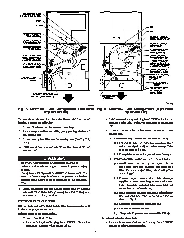
58MXB Deluxe 4Way Multipoise Fixed-Capacity Condensing Gas Furnace Visit www.carrier.com Installation, Start-Up, and Operating Instructions Sizes 040-140, Series 100 24v Wiring .26 Accessories 26 Removal of Existing Furnaces from Common Vent Systems 27 Combustion Air and Vent Pipe Systems .27 Condensate Drain 41 General .41 Application .42 Condensation Drain Protection .42 A93040 NOTE: Read the entire instruction manual before starting the installation.
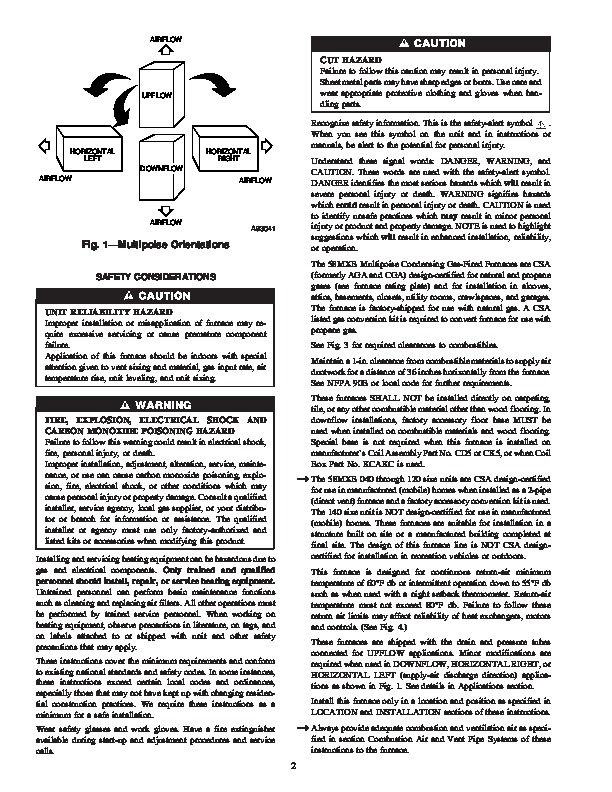
NOTE: This furnace can be installed as a (2-pipe) direct vent or (1-pipe) non-direct vent condensing gas furnace. This symbol indicates a change since the last issue. TABLE OF CONTENTS SAFETY CONSIDERATIONS .2 CODES AND STANDARDS 4 ELECTROSTATIC DISCHARGE (ESD) PRECAUTIONS 6 INTRODUCTION 6 APPLICATIONS 6 General 6 Upflow Applications .6 Downflow Applications 8 Horizontal Left (Supply-Air Discharge) Applications 10 Horizontal Right (Supply-Air Discharge) Applications 11 LOCATION 14 General 14 Furnace Location Relative to Cooling Equipment 15 Hazardous Locations .15 Furnace Location and Application .15 AIR FOR COMBUSTION AND VENTILATION 16 INSTALLATION .19 Leveling Legs (If Desired) .19 Installation in Upflow and Downflow Applications 19 Installation in Horizontal Applications 19 Air Ducts .21 General Requirements .21 Ductwork Acoustical Treatment .21 Supply Air Connections 21 Return Air Connections .21 Filter Arrangement 22 Bottom Closure Panel .23 Gas Piping .23 Electrical Connections 24 115v Wiring .25 START-UP, ADJUSTMENTS AND SAFETY CHECK .42 General 42 Prime Condensate Trap With Water 43 Purge Gas Lines 43 Sequence of Operation 43 Heating Mode 44 Cooling Mode 44 Thermidistat Mode 44 Continuous Blower Mode .47 Heat Pump Mode .47 Component Test .51 Adjustments .51 Set Gas Input Rate 51 Set Temperature Rise 55 Adjust Blower Off Delay (Heat Mode) 55 Set Thermostat Heat Anticipator 55 Check Safety Controls 56 Check Primary Limit Control .56 Check Pressure Switch 56 Checklist 56 Manufacturer reserves the right to discontinue, or change at any time, specifications or designs without notice and without incurring obligations. Book 1 4 PC 101 Printed in U.S.A. Catalog No. 58MXB-1SI Pg 1 8-05 Replaces: 58MXA-18SI Tab 6a 8a AIRFLOW UPFLOW CUT HAZARD Failure to follow this caution may result in personal injury. Sheet metal parts may have sharp edges or burrs. Use care and wear appropriate protective clothing and gloves when handling parts. Recognize safety information. This is the safety-alert symbol. When you see this symbol on the unit and in instructions or manuals, be alert to the potential for personal injury. Understand these signal words: DANGER, WARNING, and CAUTION. These words are used with the safety-alert symbol. DANGER identifies the most serious hazards which will result in severe personal injury or death. WARNING signifies hazards which could result in personal injury or death. CAUTION is used to identify unsafe practices which may result in minor personal injury or product and property damage. NOTE is used to highlight suggestions which will result in enhanced installation, reliability, or operation.