


| Categories | Carrier HVAC Manuals |
|---|---|
| Document Type | Heating, Ventilating and Air Conditioning Manual Free Download. HAVC Operator's Instruction Manual. |
| Tags | Carrier 58PA |
| Download File |
|
| Language | English |
| Product Brand | Carrier. Support Phone Number: In North America, please call 1-800-CARRIER for immediate customer assistance from 8:00a -5:00p (EST) weekdays , Heating, Ventilating and Air Conditioning - HVAC |
| Document File Type | |
| Publisher | corp.carrier.com |
| Wikipedia's Page | Carrier Corporation |
| Copyright | Attribution Non-commercial |
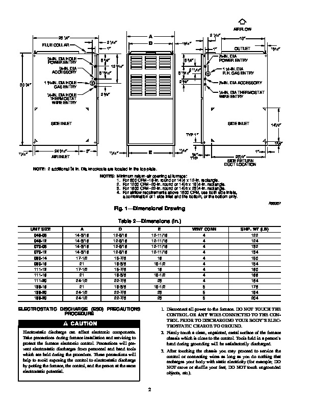
58PAV Upflow Induced-Combustion Furnaces Installation, Start-Up, and Operating Instructions Sizes 045-155, Series 151 NOTE: Read the entire instruction manual before starting the installation. This symbol indicates a change since the last issue. Index Page ® ama CANADIAN GAS ASSOCIATION A PP R O VED R SAFETY CONSIDERATIONS .1 Clearances From Combustible Materials .1 Dimensional Drawing .2 ELECTROSTATIC DISCHARGE (ESD) PRECAUTIONS PROCEDURE 2-3 INTRODUCTION 3 LOCATION 3 General 3 Location Relative to Cooling Equipment 3 Hazardous Locations .3 AIR FOR COMBUSTION AND VENTILATION .3-5 Unconfined Space .4 Confined Space 4-5 FILTER ARRANGEMENT .5-6 LEVELING LEGS (IF REQUIRED) .5-6 GAS PIPING .6-7 ELECTRICAL CONNECTIONS 7 115-v Wiring .7 24-v Wiring .7 Accessories 7 VENTING 7 START-UP, ADJUSTMENT, AND SAFETY CHECK .7-14 General .7-8 Sequence Of Operation .8-11 Heating Mode 8-9 Cooling Mode .9 Continuous Blower Mode .9 Heat Pump Mode .9-11 Start-Up Procedures 11 Adjustments .11-14 Set Gas Input Rate 11-12 Set Temperature Rise 12-13 Set Thermostat Heat Anticipator 13 Check Safety Controls 14 Checklist 14 SAFETY CONSIDERATIONS Installing and servicing heating equipment can be hazardous due to gas and electrical components.
Only trained and qualified personnel should install, repair, or service heating equipment. Untrained personnel can perform basic maintenance functions such as cleaning and replacing air filters. All other operations must be performed by trained service personnel. When working on heating equipment, observe precautions in the literature, on tags, and on labels attached to or shipped with the unit and other safety precautions that may apply. Follow all safety codes. In the United States, follow all safety codes including the National Fuel Gas Code (NFGC) NFPA No. 54-1992/ANSI Z223.1-1992. In Canada, refer to the current edition of the National Standard of Canada CAN/CGA-B149.1and .2-M91 Natural Gas and Propane Installation Codes (NSCNGPIC). Wear safety glasses and work gloves. Have fire extinguisher available during start-up and adjustment procedures and service calls. Recognize safety information. This is the safety-alert symbol. When you see this symbol on the furnace and in instructions or manuals, be alert to the potential for personal injury. Understand the signal words DANGER, WARNING, and CAUTION. These words are used with the safety-alert symbol. DANGER identifies the most serious hazards which will result in severe personal injury or death. WARNING signifies a hazard which could result in personal injury or death. CAUTION is used to identify unsafe practices which would result in minor personal injury or product and property damage. NOTE is used to highlight suggestions which will result in enhanced installation, reliability, or operation. These instructions cover minimum requirements and conform to existing national standards and safety codes. In some instances, these instructions exceed certain local codes and ordinances, especially those that may not have kept up with changing residential construction practices. We require these instructions as a minimum for a safe installation. Table 1–Minimum Clearances To Combustible Materials (In.) UNIT SIZE 045 AND 070 090-155 Single-Wall Vent 1 0 Type B-1 Double-Wall Vent 0 0 Back 0 0 Plenum Top 1 1 Vent Single-Wall Vent 6 6 Type B-1 Double-Wall Vent 1 1 Front Single-Wall Vent 6 6 Type B-1 Double-Wall Vent 3 3 Service 30 30 Sides NOTES: 1. Provide 30-in. front clearance for servicing. An open door in front of the unit can meet this requirement. 2. A minimum clearance of 3 in. must be provided in front of the unit for combustion air and proper operation. Manufacturer reserves the right to discontinue, or change at any time, specifications or designs without notice and without incurring obligations. Book 1 4 PC 101 Catalog No. 535-817 Printed in U.S.A. Form 58PA-11SI Pg 1 8-95 Replaces: 58PA-10SI Tab 6a 8a AIRFLOW 28 1/2 FLUE COLLAR SIDE RETURN DUCT LOCATION NOTE: 2 additional 7/8 In. Dia knockouts are located in the top plate. NOTES: Minimum return-air opening at furnace: 1. For 800 CFM16-In. round or 141/2 x 12-In. rectangle. 2. For 1200 CFM20-In. round or 141/2 x 191/2-In. rectangle. 3. For 1600 CFM22-In. round or 141/2 x 231/4-In. rectangle. 4. For airflow requirements above 1800 CFM, use both side inlets, a combination of 1 side inlet and the bottom, or the bottom only. PRECAUTIONS PROCEDURE Electrostatic discharge can affect electronic components. Take precautions during furnace installation and servicing to protect the furnace electronic control. Precautions will prevent electrostatic discharges from personnel and hand tools which are held during the procedure.