| Categories | Carrier HVAC Manuals |
|---|---|
| Document Type | Heating, Ventilating and Air Conditioning Manual Free Download. HAVC Operator's Instruction Manual. |
| Tags | Carrier 58SX |
| Download File |
|
| Language | English |
| Product Brand | Carrier. Support Phone Number: In North America, please call 1-800-CARRIER for immediate customer assistance from 8:00a -5:00p (EST) weekdays , Heating, Ventilating and Air Conditioning - HVAC |
| Document File Type | |
| Publisher | corp.carrier.com |
| Wikipedia's Page | Carrier Corporation |
| Copyright | Attribution Non-commercial |
Inducer Housing Kit Cancels: IIK 398A-40-14 IIK 398A-40-28 2-1-92 Installation Instructions Part No. 308088-751 NOTE: Read the entire instruction before starting the installation. INTRODUCTION This instruction covers installation of the Inducer Housing Kit, Part No. 308088-751, in an Upflow Gas-Fired Condensing Furnace. NOTE: A releasing agent (Pam cooking spray or equivalent) and RTV sealant (G.E.
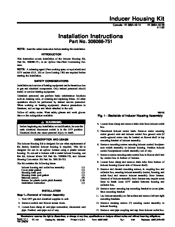
162 or Dow-Corning 738) are required before starting the installation. SAFETY CONSIDERATIONS Installation and service of heating equipment can be hazardous due to gas and electrical components. Only trained personnel should install or service heating equipment. Untrained personnel can perform basic maintenance functions such as cleaning coils, or cleaning and replacing filters. All other operations should be performed by trained service personnel. When working on heating equipment, observe precautions in literature, and on tags and labels attached to the unit. Follow all safety codes. Wear safety glasses and work gloves. Have a fire extinguisher available. A86100 Fig. 1–Backside of Inducer Housing Assembly 4. Loosen hose clamp and remove drain tube from inducer outlet box. 5. Disconnect inducer motor leads. Remove screw securing motor ground wire and inducer control box ground wire (if used)–ground screw may be located on blower shelf or top mounting bracket of inducer assembly. 6. Remove mounting screws securing inducer control box/pressure switch assembly to inducer housing. Position inducer control box/pressure switch assembly out of way. 7. Remove screws securing main control box to blower shelf and lay control box in bottom of furnace. 8. Loosen hose clamp and remove drain tube from bottom of inducer housing (lower side of blower shelf). Before beginning any installation or modification, be sure the main electrical disconnect switch is in the OFF position. Electrical shock can cause personal injury or death. DESCRIPTION AND USAGE The Inducer Housing Kit is designed for use when replacement of the factory installed inducer housing is required. This kit is designed for use in an upflow furnace using a plastic inducer housing. To convert a furnace with a metal inducer housing, use this kit, Inducer Motor Kit Part No. 309868-752, and Inducer Housing Conversion Kit Part No. 308120-752. The kit contains the following items: Inducer housing and outlet box assembly Cover plate gasket Housing drain port Housing drain port gasket Stainless screws Screws for plastic (wide pitch threads) Installation Instruction INSTALLATION Step 1–Removal of Inducer Assembly 1. Turn OFF gas and electrical supplies to unit. 2. Remove control and blower access doors. 3. Loosen hose clamp at vent pipe connection; disconnect vent pipe. Position vent pipe out of way. (1) (1) (1) (1) (5) (14) (1) 9. Remove and discard mounting screws, in coupling box and collector box, securing inducer assembly (motor, housing, and outlet box) and remove inducer assembly from furnace. Removal of inducer assembly from furnace may require some force to break loose RTV sealant between housing and collector box. 10. Remove screw securing top mounting bracket to cover plate. Save mounting bracket. 11. Lay inducer assembly on flat surface and remove left and right mounting brackets. 12. Remove remaing screws (7) securing motor assembly to inducer housing. 13. Remove vent pipe coupling and cap from inducer outlet box. Manufacturer reserves the right to discontinue, or change at any time, specifications or designs without notice and without incurring obligations. Book 1 4 PC 101 Catalog No. 565-958 Printed in U.S.A. Form 58SX-29SI Pg 1 2-92 Replaces: 58SX,SXB-2SI Tab 6a 8a Step 2–Installation of New Inducer Housing