| Categories | Carrier HVAC Manuals |
|---|---|
| Document Type | Heating, Ventilating and Air Conditioning Manual Free Download. HAVC Operator's Instruction Manual. |
| Tags | Carrier 58SX |
| Download File |
|
| Language | English |
| Product Brand | Carrier. Support Phone Number: In North America, please call 1-800-CARRIER for immediate customer assistance from 8:00a -5:00p (EST) weekdays , Heating, Ventilating and Air Conditioning - HVAC |
| Document File Type | |
| Publisher | corp.carrier.com |
| Wikipedia's Page | Carrier Corporation |
| Copyright | Attribution Non-commercial |
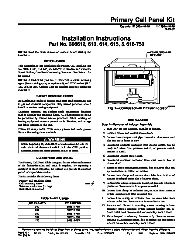
Primary Cell Panel Kit Cancels: IIK 398A-40-19 IIK 398A-40-29 3-15-92 Installation Instructions Part No. 308612, 613, 614, 615, & 616-753 NOTE: Read the entire instruction manual before starting the installation. INTRODUCTION This instruction covers installation of a Primary Cell Panel Kit Part No. 308612, 613, 614, 615, and 616-753 in Standard and VariableSpeed Upflow, Gas-Fired Condensing Furnaces.
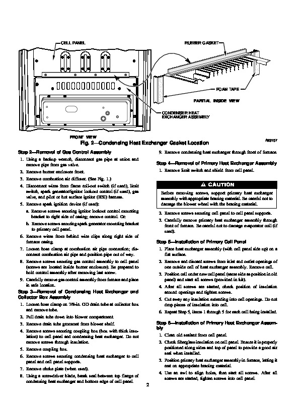
(See Table 1 for kit usage.) NOTE: A Gasket Kit (Part No. 318050-751), a sealant releasing agent (Pam cooking spray or equivalent), and RTV sealant (G.E. 122, 162, or Dow-Corning 738) are required prior to starting the installation. SAFETY CONSIDERATIONS Installation and service of heating equipment can be hazardous due to gas and electrical components. Only trained personnel should install or service heating equipment. Untrained personnel can perform basic maintenance functions such as cleaning and replacing filters. All other operations should be performed by trained service personnel. When working on heating equipment, observe precautions in literature, and on tags and labels attached to the unit. Follow all safety codes. Wear safety glasses and work gloves. Have a fire extinguisher available. COMBUSTION-AIR DIFFUSER Fig. 1–Combustion-Air Diffuser Location A84153 INSTALLATION Step 1–Removal of Inducer Assembly 1. Turn OFF gas and electrical supplies to furnace. 2. Remove blower and control access doors. 3. Loosen hose clamp at vent pipe connection; disconnect vent pipe and move it out of way. Before beginning any installation or modification, be sure the main electrical disconnect switch is in the OFF position. Electrical shock can cause personal injury or death. DESCRIPTION AND USAGE The Primary Cell Panel Kit is designed for use when replacement of the factory-installed cell panel is required. By replacing a damaged or failed cell panel, the furnace will provide an extended period of dependable service. The kit contains the following items: Primary cell panel (insulated) Cell mounting screw Stainless steel screw (in bag) Installation Instruction 1 max 49 11 1 4. Disconnect electrical connector from inducer control box (if used) and wires from pressure switch, or pressure switch harness (if used). 5. Disconnect inducer motor leads. 6. Disconnect electrical connector from main control box at blower shelf. 7. Remove screws securing main control box to blower shelf and lay control box in bottom of furnace. 8. Loosen hose clamp and remove drain tube from bottom of inducer housing (bottom side of blower shelf). 9. Loosen hose clamp, at pressure switch, on pressure tube from plastic tee. Remove tube from pressure switch. 10. Loosen hose clamp, at collector box, on tube from pressure switch. Remove tube from collector box.