| Categories | Carrier HVAC Manuals |
|---|---|
| Document Type | Heating, Ventilating and Air Conditioning Manual Free Download. HAVC Operator's Instruction Manual. |
| Tags | Carrier 58SXB |
| Download File |
|
| Language | English |
| Product Brand | Carrier. Support Phone Number: In North America, please call 1-800-CARRIER for immediate customer assistance from 8:00a -5:00p (EST) weekdays , Heating, Ventilating and Air Conditioning - HVAC |
| Document File Type | |
| Publisher | corp.carrier.com |
| Wikipedia's Page | Carrier Corporation |
| Copyright | Attribution Non-commercial |
ICM-2* Motor Conversion Kit Cancels: IIK 398B-60-3 IIK 320A-60-1 7-15-92 Installation Instructions Part No. 319345-751 and -752 NOTE: Read the entire instruction manual before starting the installation. *Integral Control Motor (ICM-2 denotes second generation). INTRODUCTION This instruction covers installation of an ICM-2 Motor Conversion Kit Part No. 319345-751 and -752 in upflow, gas-fired, variablespeed condensing furnaces.
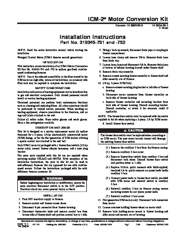
NOTE: Due to the reduced accessibility to the filter caused by the ICM motor on right-side, return-air installations, an accessory side filter rack may be required to complete the installation. SAFETY CONSIDERATIONS Installation and service of heating equipment can be hazardous due to gas and electrical components. Only trained personnel should install or service heating equipment. Untrained personnel can perform basic maintenance functions such as cleaning and replacing filters. All other operations should be performed by trained service personnel. When working on heating equipment, observe precautions in the literature, and on tags and labels attached to the unit. Follow all safety codes. Wear safety glasses and work gloves. Have a fire extinguisher available. DESCRIPTION AND USAGE This kit is designed as a service replacement motor (in upflow furnaces) for a 2-piece, 1/3-hp electronically commutated motor (ECM) design, or for the first generation of ICM motors utilizing a square control box attached to the end bell. Each ICM-2 motor is packaged with a blower door switch (1/2-hp motor only), several blower adapter harnesses, and a new plug bracket. The extra parts supplied with this kit are not required when servicing models 320AAZ and 58VUA. With exception of the Installation Instructions, the parts in this kit can be used in mid-efficiency furnaces that are approved for use with variablespeed motors. Follow the instructions packaged with the midefficiency furnace accessory kit. 5. Using a back-up wrench, disconnect drain pipe at coupling in blower compartment. 6. Loosen hose clamp and remove 7/8-in. diameter drain hose from drain trap. 7. Loosen hose clamp and disconnect 5/8-in. diameter drain hose at bottom of inducer housing located under blower shelf. 8. Remove drain trap assembly. 9. Remove screws securing blower assembly to blower shelf and slide assembly out of furnace. 10. 1/3-hp, 2-piece ECM Only: a. Remove screws securing plug bracket to left side of blower housing. b. Disconnect motor connector from blower controller on back side of blower housing. c. Remove blower controller and mounting brackets from back side of blower housing. Discard mounting bracket. Discard controller, or return it for warranty credit if applicable. NOTE: The blower door switch must be replaced with the switch supplied in the kit when replacing a 2-piece, 1/3-hp ECM motor. d. Install blower door switch. The blower door switch must be replaced when converting to an ICM motor. The new motor in-rush current will damage the existing blower door switch. (1.) Remove the auxiliary J-box from the furnace casing. (2.) Remove auxiliary J-box cover. (3.) Remove blower door switch from auxiliary J-box and disconnect both wires. Discard blower door switch and position wires to 1 side. (4.) Replace 3/16-in. quick connects with field-supplied, insulated 1/4-in. quick connects on power leads inside auxiliary J-box. (5.) Connect power leads to blower door switch provided with ICM motor and reinstall switch in auxiliary J-box. (6.) Reinstall auxiliary J-box on furnace casing; ensure mounting screws do not pierce power leads.