| Categories | Carrier HVAC Manuals |
|---|---|
| Document Type | Heating, Ventilating and Air Conditioning Manual Free Download. HAVC Operator's Instruction Manual. |
| Tags | Carrier 58ZAV |
| Download File |
|
| Language | English |
| Product Brand | Carrier. Support Phone Number: In North America, please call 1-800-CARRIER for immediate customer assistance from 8:00a -5:00p (EST) weekdays , Heating, Ventilating and Air Conditioning - HVAC |
| Document File Type | |
| Publisher | corp.carrier.com |
| Wikipedia's Page | Carrier Corporation |
| Copyright | Attribution Non-commercial |
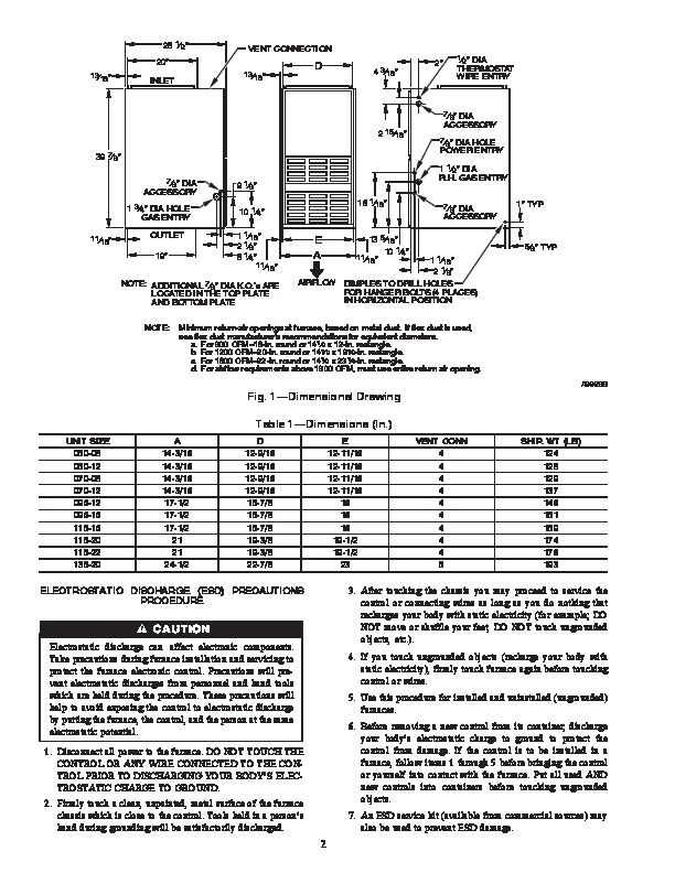
WeatherMaker 8000TM 58ZAV Downflow/Horizontal Induced-Combustion Furnaces Visit www.carrier.com Installation, Start-Up, and Operating Instructions Sizes 050–135, Series 151 and 161 NOTE: Read the entire instruction manual before starting the installation. This symbol indicates a change since the last issue. Index Page SAFETY CONSIDERATIONS .1 ELECTROSTATIC DISCHARGE (ESD) PRECAUTIONS PROCEDURE .2 INTRODUCTION .3-4 Dimensional Drawing .2 Clearances From Combustible Materials .3 LOCATION 4 General 4 Location Relative to Cooling Equipment 4 Hazardous Locations .4 AIR FOR COMBUSTION AND VENTILATION .4-5 Unconfined Space 4-5 Confined Space .5 AIR DUCTS 5-6 General Requirements .5 Ductwork Acoustical Treatment .5 Supply-Air Connections 6 Return-Air Connections 6 DOWNFLOW INSTALLATION 7 HORIZONTAL ATTIC INSTALLATION .9 Construct a Working Platform .9 Install Furnace .9 HORIZONTAL CRAWLSPACE INSTALLATION 9 FILTER ARRANGEMENT .9 GAS PIPING 9 ELECTRICAL CONNECTIONS .10-12 115-v Wiring .10 24-v Wiring .11 Accessories 11-12 VENTING 12 START-UP, ADJUSTMENT, AND SAFETY CHECK .12-21 General 12 Sequence Of Operation .13 Heating Mode 12 Cooling Mode .15 Continuous Blower Mode .15 Heat Pump Mode 15 Start-up Procedures .15 Adjustments .15-21 Set Gas Input Rate 15 Set Temperature Rise 19 Set Thermostat Heat Anticipator 20 Check Safety Controls 20 Checklist 21 ama CERTIFIED ® REGISTERED QUALITY SYSTEM SAFETY CONSIDERATIONS Installing and servicing heating equipment can be hazardous due to gas and electrical components.
Heating, Ventilating and Air Conditioning User Manual Free Download. HAVC Operator’s Manual. Gas Furnace and AC Free Instruction Manual Download PDF.
Only trained and qualified personnel should install, repair, or service heating equipment. Untrained personnel can perform basic maintenance functions such as cleaning and replacing air filters. All other operations must be performed by trained service personnel. When working on heating equipment, observe precautions in the literature, on tags, and on labels attached to or shipped with the unit and other safety precautions that may apply. In the United States, follow all safety codes including the National Fuel Gas Code (NFGC) NFPA 54-1999/ANSI Z223.1-1999 and the Installation Standards, Warm Air Heating and Air Conditioning Systems (NFPA 90B) ANSI/NFPA 90B. In Canada, refer to the CAN/CGA-B149.1- and .2-M95 National Standard of Canada, Natural Gas and Propane Installation Codes (NSCNGPIC). Wear safety glasses and work gloves. Have fire extinguisher available during start-up and adjustment procedures and service calls. Recognize safety information. This is the safety-alert symbol. When you see this symbol on the furnace and in instructions or manuals, be alert to the potential for personal injury. Understand the signal words DANGER, WARNING, CAUTION, and NOTE. These words are used with the safety-alert symbol. DANGER identifies the most serious hazards which will result in severe personal injury or death. WARNING signifies a hazard which could result in personal injury or death. CAUTION is used to identify unsafe practices which would result in minor personal injury or product and property damage. NOTE is used to highlight suggestions which will result in enhanced installation, reliability, or operation. These instructions cover minimum requirements and conform to existing national standards and safety codes. In some instances, these instructions exceed certain local codes and ordinances, especially those that may not have kept up with changing residential construction practices. We require these instructions as a minimum for a safe installation. Manufacturer reserves the right to discontinue, or change at any time, specifications or designs without notice and without incurring obligations. Book 1 4 PC 101 Catalog No. 535-768 Printed in U.S.A. Form 58ZAV-12SI Pg 1 10-00 Replaces: 58ZAV-10SI Tab 6a 8a 28 1/2 20 13/16 VENT CONNECTION 13/16 D INLET 4 3/16 2 1/2 DIA THERMOSTAT WIRE ENTRY 7/8 DIA 2 15/16 39 7/8 7/8 DIA ACCESSORY 7/8 DIA HOLE POWER ENTRY ACCESSORY 1 3/4 DIA HOLE GAS ENTRY 11/16 9 1/8 10 1/4 1 1/16 2 1/8 8 1/4 16 1/16 1 1/2 DIA R.H. GAS ENTRY 7/8 DIA 1 TYP ACCESSORY 5/8 TYP OUTLET E A 19 11/16 NOTE: ADDITIONAL 7/8 DIA K.O.’s ARE LOCATED IN THE TOP PLATE AND BOTTOM PLATE NOTE: 1 1/16 2 1/8 AIRFLOW DIMPLES TO DRILL HOLES FOR HANGER BOLTS (4 PLACES) IN HORIZONTAL POSITION 13 5 /16 10 1/4 11/16 Minimum return-air openings at furnace, based on metal duct. If flex duct is used, see flex duct manufacturer’s recommendations for equivalent diameters. a. For 800 CFM16-in. round or 141/2 x 12-in. rectangle. b. For 1200 CFM20-in. round or 141/2 x 191/2-in. rectangle. c. For 1600 CFM22-in. round or 141/2 x 231/4-in. rectangle. d. For airflow requirements above 1800 CFM, must use entire return air opening. A99288 Fig. 1–Dimensional Drawing Table 1–Dimensions (In.) UNIT SIZE 050-08 050-12 070-08 070-12 096-12 096-16 115-16 115-20 115-22 135-20 A 14-3/16 14-3/16 14-3/16 14-3/16 17-1/2 17-1/2 17-1/2 21 21 24-1/2 D 12-9/16 12-9/16 12-9/16 12-9/16 15-7/8 15-7/8 15-7/8 19-3/8 19-3/8 22-7/8 E 12-11/16 12-11/16 12-11/16 12-11/16 16 16 16 19-1/2 19-1/2 23 VENT CONN 4 4 4 4 4 4 4 4 4 5 SHIP. WT (LB) 124 128 129 137 146 151 159 174 176 193 ELECTROSTATIC DISCHARGE (ESD) PRECAUTIONS PROCEDURE Electrostatic discharge can affect electronic components. Take precautions during furnace installation and servicing to protect the furnace electronic control. Precautions will prevent electrostatic discharges from personnel and hand tools which are held during the procedure. These precautions will help to avoid exposing the control to electrostatic discharge by putting the furnace, the control, and the person at the same electrostatic potential. 1. Disconnect all power to the furnace. DO NOT TOUCH THE CONTROL OR ANY WIRE CONNECTED TO THE CONTROL ….. …