| Categories | Carrier HVAC Manuals |
|---|---|
| Document Type | Heating, Ventilating and Air Conditioning Manual Free Download. HAVC Operator's Instruction Manual. |
| Tags | Carrier 58ZAV |
| Download File |
|
| Language | English |
| Product Brand | Carrier. Support Phone Number: In North America, please call 1-800-CARRIER for immediate customer assistance from 8:00a -5:00p (EST) weekdays , Heating, Ventilating and Air Conditioning - HVAC |
| Document File Type | |
| Publisher | corp.carrier.com |
| Wikipedia's Page | Carrier Corporation |
| Copyright | Attribution Non-commercial |
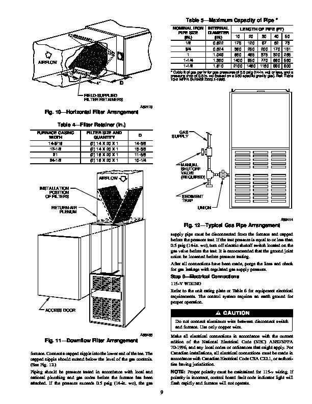
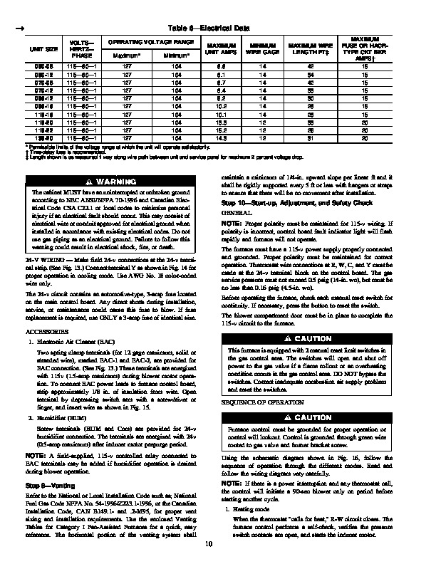
WeatherMaker 8000TM 58ZAV Downflow/Horizontal Induced-Combustion Furnaces Visit www.carrier.com Installation, Start-Up, and Operating Instructions Sizes 050–135, Series 141 NOTE: Read the entire instruction manual before starting the installation. This symbol indicates a change since the last issue. Index Page ® A PP R O VED R ama CANADIAN GAS ASSOCIATION SAFETY CONSIDERATIONS 1-2 Clearances From Combustible Materials .1 Dimensional Drawing .2 ELECTROSTATIC DISCHARGE (ESD) PRECAUTIONS PROCEDURE 2-3 INTRODUCTION 3 LOCATION 3-4 General 3 Location Relative to Cooling Equipment 3 Hazardous Locations .4 AIR FOR COMBUSTION AND VENTILATION .4-5 Unconfined Space .4 Confined Space 4-5 SUPPLY-AIR PLENUM INSTALLATION (DOWNFLOW) 5-6 Downflow Installation .5 Installation On a Combustible Floor 5-6 HORIZONTAL ATTIC INSTALLATION .6 Construct a Working Platform .6 Install Furnace .6 HORIZONTAL CRAWLSPACE INSTALLATION 6 FILTER ARRANGEMENT .7 GAS PIPING .7-9 ELECTRICAL CONNECTIONS .9-10 115-v Wiring 9-10 24-v Wiring .10 Accessories 10 VENTING 10 START-UP, ADJUSTMENT, AND SAFETY CHECK .10-18 General 10 Sequence Of Operation .10-12 Heating Mode 12 Cooling Mode .12 Continuous Blower Mode .12 Heat Pump Mode 12 Start-up Procedures 12-14 Adjustments .14-18 Set Gas Input Rate 14-17 Set Temperature Rise 17-18 Set Thermostat Heat Anticipator 18 Check Safety Controls .18-19 Checklist 19 SAFETY CONSIDERATIONS Installing and servicing heating equipment can be hazardous due to gas and electrical components.
Heating, Ventilating and Air Conditioning User Manual Free Download. HAVC Operator’s Manual. Gas Furnace and AC Free Instruction Manual Download PDF.
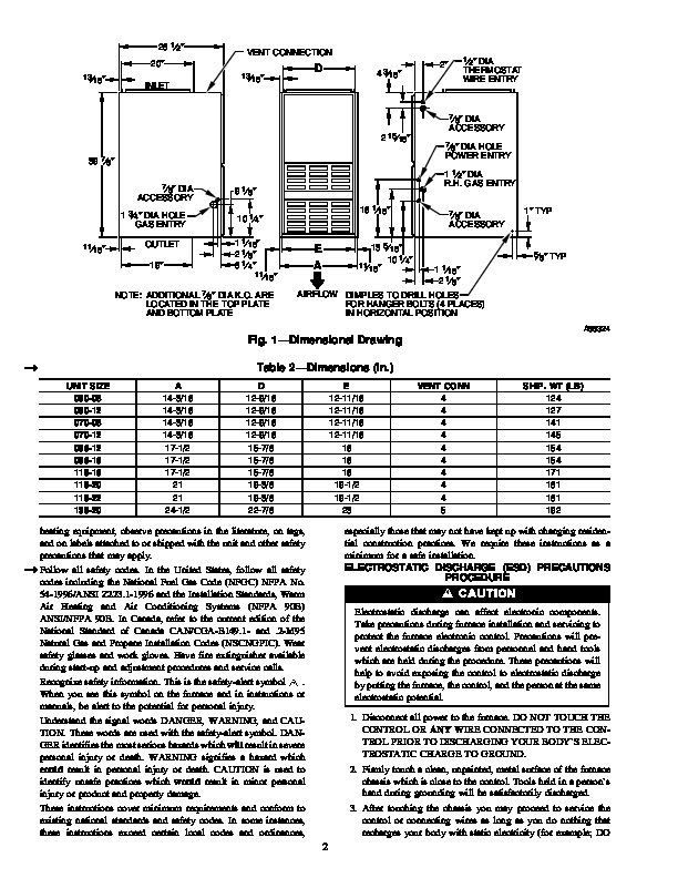
Only trained and qualified personnel should install, repair, or service heating equipment. Untrained personnel can perform basic maintenance functions such as cleaning and replacing air filters. All other operations must be performed by trained service personnel. When working on Table 1–Clearances From Combustible Materials (In.) UNIT SIZE 050 AND 070 096-135 DOWNFLOW (In Alcove or Closet) Single-Wall Vent 1 0 Type B-1 Double-Wall Vent 0 0 0 0 1 1 Single-Wall Vent 6 6 Type B-1 Double-Wall Vent 3 3 Single-Wall Vent 6 6 Type B-1 Double-Wall Vent 1 1 HORIZONTAL (Attic, Alcove, or Crawlspace) 1 0 0 0 Single-Wall Vent 1 1 Type B-1 Double-Wall Vent 1 1 Single-Wall Vent 6 6 Type B-1 Double-Wall Vent 3 3 Single-Wall Vent 6 6 Type B-1 Double-Wall Vent 1 1 HORIZONTAL (In Closet) 1 1 3 3 Single-Wall Vent 2 2 Type B-1 Double-Wall Vent 2 2 Single-Wall Vent 6 6 Type B-1 Double-Wall Vent 3 3 Single-Wall Vent 6 6 Type B-1 Double-Wall Vent 1 1 Sides Back Top Front Vent Sides * Back Top Front Vent Sides * Back Top Front Vent * Indicates supply or return sides when furnace is in the horizontal position. Clearance shown is for outlet end. The inlet end must maintain 6-in. minimum clearance from the vent to combustible materials when using single-wall vent. Minimum 18-in. front clearance required for alcove. NOTES: 1. Provide 30-in. front clearance for servicing. An open door in front of the furnace can meet this requirement. 2. A minimum clearance of 3 in. must be provided in front of the furnace for combustion air and proper operation. 3. Line contact is permitted as shown in Fig. 7. Manufacturer reserves the right to discontinue, or change at any time, specifications or designs without notice and without incurring obligations. Book 1 4 PC 101 Catalog No. 535-860 Printed in U.S.A. Form 58ZAV-9SI Pg 1 1-97 Replaces: 58ZAV-8SI Tab 6a 8a 28 1/2 20 13/16 VENT CONNECTION 13/16 D 4 3/16 2 1/2 DIA INLET THERMOSTAT WIRE ENTR