| Categories | Carrier HVAC Manuals |
|---|---|
| Document Type | Heating, Ventilating and Air Conditioning Manual Free Download. HAVC Operator's Instruction Manual. |
| Tags | Carrier 73 |
| Download File |
|
| Language | English |
| Product Brand | Carrier. Support Phone Number: In North America, please call 1-800-CARRIER for immediate customer assistance from 8:00a -5:00p (EST) weekdays , Heating, Ventilating and Air Conditioning - HVAC |
| Document File Type | |
| Publisher | corp.carrier.com |
| Wikipedia's Page | Carrier Corporation |
| Copyright | Attribution Non-commercial |
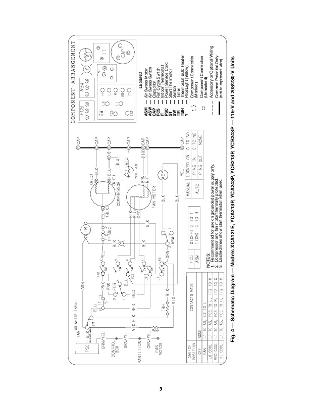
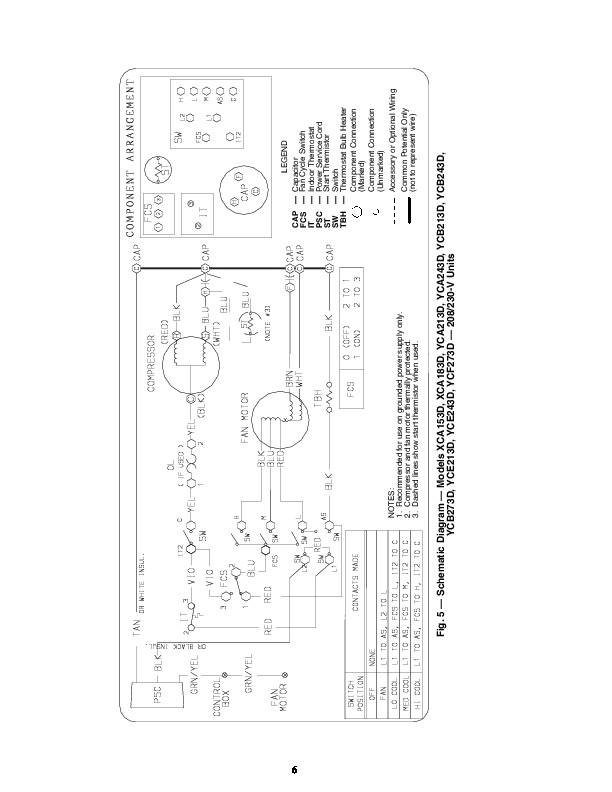
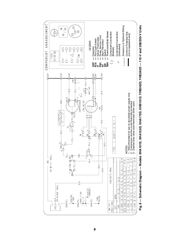
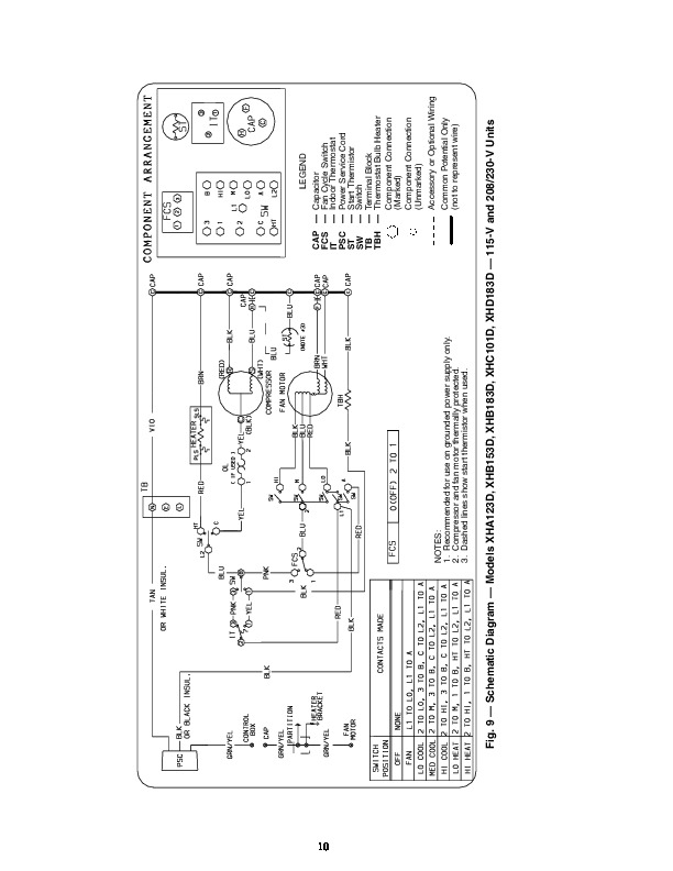
73AC,XC,XH,XQ,YC,YH Series Room Air Conditioners 1998-2003 Wiring Diagrams 73 SERIES ROOM AIR CONDITIONERS INDEX MODEL NO. 73 ACA051B ACA051T, ACA061T, ACA081T, ACA101P, ACA121T XCA101D, XCA121D, XCA141D, XCD121D, XCE101D XCA123D, XCB123D, XCB153D, XCB183D, XCE183D XCA121E XCA153D, XCA183D XCB183E XCB183L XHA101D, XHB101D XHA153D, XHA173D XHC101D XHA123D, XHB153D, XHB183D, XHD183D XQA101D XQB101D XQA123D, XQB153D, XQB183D YCA213D, YCA243D, YCB213D, YCB243D, YCB273D, YCE213D, YCE243D, YCF273D YCA213P, YCA243P, YCB213P, YCB243P YCB213E, YCB243E YHB243D, YHE243D
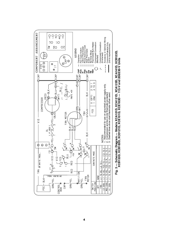
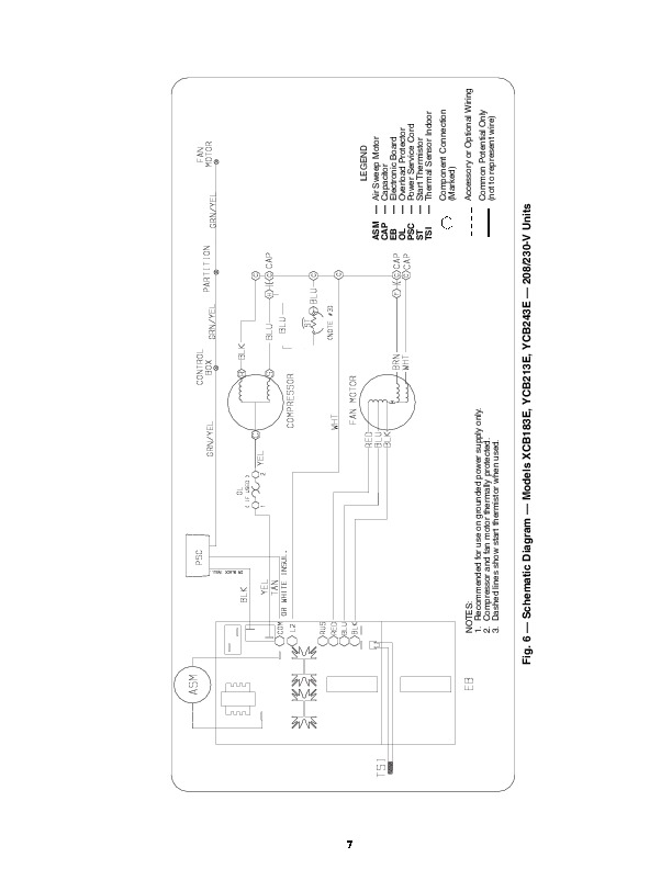
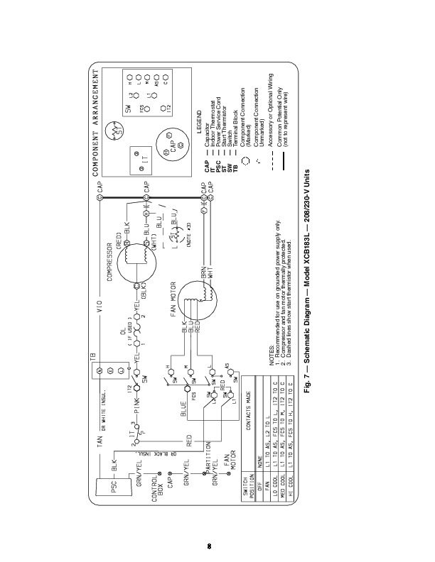
(SCHEMATIC DESIGNATOR) 309107301 309364201 11708001 (E)* 11708001 (E)* 11708001 (C)* 11708001 (A)* 11708122 (A) 11708001 (F) 11708008 (A)* 11708008 (A)* 11708008 (D)* 11708008 (D)* 11708008 (B) 11708008 (E)* 11708008 (E)* 11708001 (A) FIGURE NO. Air Sweep Motor Air Sweep Switch Capacitor Fan Cycle Switch Indoor Thermostat Power Service Cord Start Thermistor Switch Timer Thermostat Bulb Heater Pilot Light (Yellow) Component Connection (Marked) Component Connection (Unmarked) Accessory or Optional Wiring Common Potential Only (not to represent wire) Fig. 4 — Schematic Diagram — Models XCA121E, YCA213P, YCA243P, YCB213P, YCB243P — 115-V and 208/230-V Units 6 NOTES: 1. Recommended for use on grounded power supply only. 2. Compressor and fan motor thermally protected. 3. Dashed lines show start thermistor when used. CAP FCS IT PSC ST SW TBH — — — — — — — LEGEND Capacitor Fan Cycle Switch Indoor Thermostat Power Service Cord Start Thermistor Switch Thermostat Bulb Heater Component Connection (Marked) Component Connection (Unmarked) Accessory or Optional Wiring Common Potential Only (not to represent wire) Fig. 5 — Schematic Diagram — Models XCA153D, XCA183D, YCA213D, YCA243D, YCB213D, YCB243D, YCB273D, YCE213D, YCE243D, YCF273D — 208/230-V Units 7 ASM CAP EB OL PSC ST TSI — — — — — — — LEGEND Air Sweep Motor Capacitor Electronic Board Overload Protector Power Service Cord Start Thermistor Thermal Sensor Indoor Component Connection (Marked) Accessory or Optional Wiring Common Potential Only (not to represent wire) NOTES: 1. Recommended for use on grounded power supply only. 2. Compressor and fan motor thermally